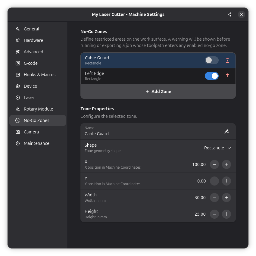
No-Go Zones
No-go zones define restricted areas on the work surface that the laser should not enter. When enabled, they are checked as part of the job sanity checks before running or exporting.
Adding a No-Go Zone
Open Settings → Machine and navigate to the No-Go Zones page. Click the add button to create a new zone, then choose its shape and position.
Each zone has the following settings:
- Name: A descriptive label for the zone
- Enabled: Toggle the zone on or off without deleting it
- Shape: Rectangle, Box, or Cylinder
- Position (X, Y, Z): Where the zone is placed on the work surface
- Dimensions: Width, height, and depth (or radius for cylinders)
Visibility
No-go zones are displayed on both the 2D and 3D canvas as semi-transparent overlays. Use the no-go zone toggle button in the canvas overlay to show or hide them. The visibility setting is remembered between sessions.
Related Pages
- Hardware Settings - Machine dimensions and axis configuration
- Job Sanity Checks - Pre-job validation
- 3D View - 3D toolpath visualization