


Hardware Settings
The Hardware page in Machine Settings configures the physical dimensions, coordinate system, and movement limits of your machine.
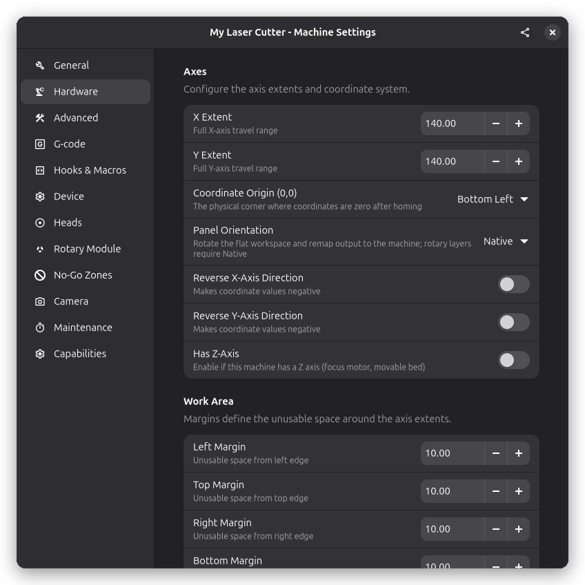
Axes
Configure the axis extents and coordinate system for your machine.
X/Y Extent
The full travel range of each axis in machine units.
- Measure the actual cutting area, not the machine exterior
- Account for any obstructions or limits
- Example: 400 for a typical K40 laser
Coordinate Origin
Select where your machine's coordinate origin (0,0) is located. This determines how coordinates are interpreted.
- Bottom Left: Most common for GRBL devices. X increases to the right, Y increases upward.
- Top Left: Common for some CNC-style machines. X increases to the right, Y increases downward.
- Top Right: X increases to the left, Y increases downward.
- Bottom Right: X increases to the left, Y increases upward.
Finding Your Origin
- Home your machine using the Home button
- Observe where the laser head moves to
- That position is your (0,0) origin
The coordinate origin setting affects how G-code is generated. Make sure it matches your firmware's homing configuration.
Axis Direction
Reverse the direction of any axis if needed:
- Reverse X-Axis Direction: Makes X coordinate values negative
- Reverse Y-Axis Direction: Makes Y coordinate values negative
- Reverse Z-Axis Direction: Enable if a positive Z command (e.g., G0 Z10) moves the head down
Z-Axis
Not every laser has a Z axis — many simple 2-axis diode machines do not. Use these settings to tell Rayforge whether your machine can move in Z:
- Has Z-Axis: Enable if this machine has a Z axis (focus motor, movable bed, or gantry that can move vertically). When disabled, the Z axis is treated as absent: no Z moves are generated, and the 3D canvas layers content at the engrave plane instead of showing a moving head along Z.
- Reverse Z-Axis Direction: Only shown when Has Z-Axis is enabled. Enable if a positive Z command (e.g., G0 Z10) moves the head down.
- Z Min / Z Max: Only shown when Has Z-Axis is enabled. The lowest and highest Z coordinate in the machine frame. Z jog moves are clamped to this range, and the Move to Position popover accepts the full Z range between the two values.
Panel Orientation
The panel orientation rotates the flat workspace as it is presented on screen and remaps output back to the machine. This is useful when a physically portrait-oriented bed is easier to edit in landscape.
- Native: The workspace is shown exactly as the machine is oriented
- Rotate Left: The workspace is rotated 90 degrees counter-clockwise
- Rotate Right: The workspace is rotated 90 degrees clockwise
Rotary layers require the Native orientation.
Work Area
Margins define the unusable space around the edges of your axis extents. This is useful when your machine has areas where the laser cannot reach (e.g., due to the laser head assembly, cable chains, or other obstructions).
- Left/Top/Right/Bottom Margin: The unusable space from each edge in machine units
When margins are set, the work area (usable space) is calculated as the axis extents minus the margins.
Soft Limits
Configurable safety bounds for jogging the machine head. When enabled, the jog controls will prevent movement outside these limits.
- Enable Custom Soft Limits: Toggle to use custom limits instead of the work surface bounds
- X/Y Min: Minimum coordinate for each axis
- X/Y Max: Maximum coordinate for each axis
Soft limits are automatically constrained to stay within the axis extents (0 to extent value).
Use soft limits to protect areas of your work surface that should never be reached during jogging, such as areas with fixtures or sensitive equipment.
See Also
- General Settings - Machine name and speed settings
- Device Settings - GRBL homing and axis settings