Laser Settings
The Laser page in Machine Settings configures your laser head(s) and their properties.
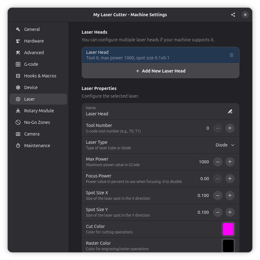
Laser Heads
Rayforge supports machines with multiple laser heads. Each laser head has its own configuration.
Adding a Laser Head
Click the Add Laser button to create a new laser head configuration.
Laser Head Properties
Each laser head has the following settings:
Name
A descriptive name for this laser head.
Examples:
- "10W Diode"
- "CO2 Tube"
- "Infrared Laser"
Tool Number
The tool index for this laser head. Used in G-code with the T command.
- Single-head machines: Use 0
- Multi-head machines: Assign unique numbers (0, 1, 2, etc.)
Maximum Power
The maximum power value for your laser.
- GRBL typical: 1000 (S0-S1000 range)
- Some controllers: 255 (S0-S255 range)
- Percentage mode: 100 (S0-S100 range)
This value should match your firmware's $30 setting.
Frame Power
The power level used for framing operations (outlining without cutting).
- Set to 0 to disable framing
- Adjust based on your laser and material
Frame Speed
The speed at which the laser head moves during framing. This is set per laser head, so if your machine has multiple lasers with different characteristics you can choose an appropriate speed for each one. Slower speeds make the frame path easier to follow by eye.
Focus Power
The power level used when focus mode is enabled. Focus mode turns on the laser at low power to act as a "laser pointer" for positioning.
- Set to 0 to disable the focus mode feature
- Use for visual alignment and positioning
Click the focus button (laser icon) in the toolbar to toggle focus mode. The laser will turn on at this power level, helping you see exactly where the laser is positioned. See Workpiece Positioning for more information.
Spot Size
The physical size of your focused laser beam in millimeters.
- Enter both X and Y dimensions
- Most lasers have a circular spot (e.g., 0.1 x 0.1)
- Affects engraving quality calculations
To measure your spot size:
- Fire a short pulse at low power on a test material
- Measure the resulting mark with calipers
- Use the average of multiple measurements
Cut Color
The color used to display cutting operations for this laser in the canvas and 3D preview. This helps you visually distinguish which laser will perform each cutting operation when working with multiple laser heads.
- Click the color swatch to open a color picker
- Choose a color that contrasts well with your material preview
- Default colors are assigned automatically
Raster Color
The color used to display raster/engraving operations for this laser in the canvas and 3D preview.
- Click the color swatch to open a color picker
- Useful for differentiating raster operations from cuts
- Each laser can have its own distinct raster color
When using multiple laser heads, assigning different colors to each laser makes it easy to see which operations will be performed by which laser. For example, use red for your main cutting laser and blue for a secondary engraving laser.
Laser Type
Choose the type of laser head from the dropdown:
- Diode: Standard diode lasers (most common for hobbyist machines)
- CO2: CO2 tube lasers
- Fiber: Fiber lasers
When CO2 or Fiber is selected, additional PWM settings become available (see below). For diode lasers, the PWM section is hidden since it does not apply.
PWM Settings
When a CO2 or Fiber laser type is selected, the following PWM controls appear:
- PWM Frequency: The default PWM frequency in Hz for this laser head. Typical values range from 500 Hz to several kHz depending on your controller and power supply.
- Max PWM Frequency: The upper limit for the frequency setting. This prevents entering values that your hardware cannot handle.
- Pulse Width: The default pulse width in microseconds. This controls how long each pulse is on during a cycle.
- Min/Max Pulse Width: Bounds for the pulse width setting.
These defaults carry through to your operation steps, where they can be overridden per step if needed.
3D Model
Each laser head can have a 3D model assigned to it. This model is rendered in the 3D view and follows the toolpath during simulation.
Click the model selection row to browse available models. Once a model is selected, you can adjust its scale, rotation (X/Y/Z), and focal distance to match your physical laser head.
See Also
- Device Settings - GRBL laser mode settings
- Workpiece Positioning - Using focus mode and other positioning methods