Contour Cutting
Contour cutting traces the outline of vector shapes to cut them free from material. It's the most common laser operation for creating parts, signs, and decorative pieces.
Overview
Contour operations:
- Follow vector paths (lines, curves, shapes)
- Cut along the perimeter of objects
- Support single or multiple passes for thick materials
- Can use inside, outside, or on-line cutting paths
- Work with any closed or open vector shape
When to Use Contour
Use contour cutting for:
- Cutting parts free from stock material
- Creating outlines and borders
- Cutting shapes from wood, acrylic, cardboard
- Perforating or scoring (with reduced power)
- Creating stencils and templates
Don't use contour for:
- Filling areas (use Engrave instead)
- Bitmap images (convert to vectors first)
Creating a Contour Operation
Step 1: Select Objects
- Import or draw vector shapes on the canvas
- Select the objects you want to cut
- Ensure shapes are closed paths for complete cuts
Step 2: Add Contour Operation
- Menu: Operations Add Contour
- Shortcut: ctrl+shift+c
- Right-click: Context menu Add Operation Contour
Step 3: Configure Settings
Key Settings
Power & Speed
Power (%):
- Laser intensity from 0-100%
- Higher power for thicker materials
- Lower power for scoring or marking
Speed (mm/min):
- How fast the laser moves
- Slower = more energy = deeper cut
- Faster = less energy = lighter cut
Multi-Pass Cutting
For materials thicker than a single pass can cut:
Passes:
- Number of times to repeat the cut
- Each pass cuts deeper
Pass Depth (Z-step):
- How much to lower Z-axis per pass (if supported)
- Requires Z-axis control on your machine
- Creates true 2.5D cutting
- Set to 0 for same-depth multiple passes
Pass depth only works if your machine has Z-axis control. For machines without Z-axis, use multiple passes at the same depth.
Path Offset
Controls where the laser cuts relative to the vector path:
| Offset | Description | Use For |
|---|---|---|
| On Line | Cuts directly on the path | Centerline cuts, scoring |
| Inside | Cuts inside the shape | Parts that must fit exact size |
| Outside | Cuts outside the shape | Holes that parts fit into |
Offset Distance:
- How far inside/outside to offset (mm)
- Typically set to half your kerf width
- Kerf = width of material removed by laser
- Example: 0.15mm offset for 0.3mm kerf
Cut Direction
Clockwise vs Counter-Clockwise:
- Affects which side of the cut gets more heat
- Usually clockwise for right-hand rule
- Change if one side burns more than the other
Optimize Order:
- Automatically sorts paths for minimum travel
- Reduces job time
- Prevents missed cuts
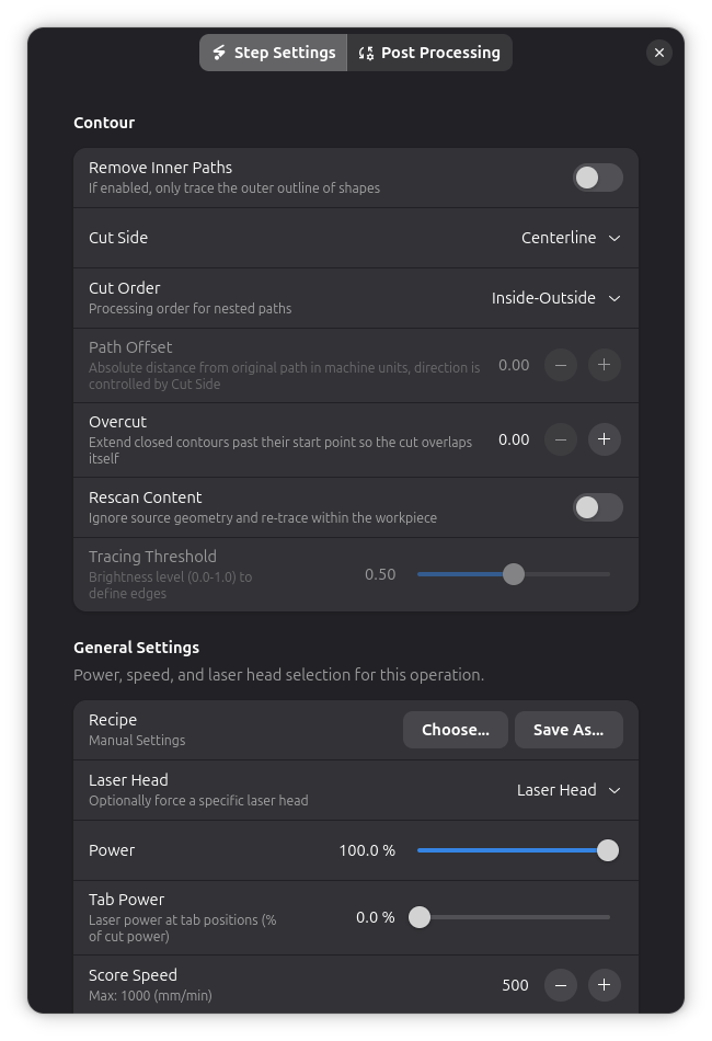
Overcut
Extends closed cutting paths past their start point so the laser beam overlaps with the beginning of the cut:
Overcut:
- Distance in machine units to extend the cut beyond the start/end junction
- Set to 0 to disable (default)
- Typical values: 1–5 for most materials
- Maximum: 100
Why use overcut:
At the start and end of a closed contour, the laser may not fully penetrate due to acceleration and deceleration. Overcut ensures the beam overlaps at the junction, creating a clean, fully severed cut. This is especially useful for:
- Thick materials where full penetration is marginal
- High-speed cutting where acceleration effects are more pronounced
- Parts that must fall free without post-processing
Overcut applies to both outer contours and internal holes.
Lead-In/Out adds zero-power approach and exit moves before and after the cut path. Overcut extends the cut path itself past the junction. They can be used together for optimal cut quality.
Post-Processing
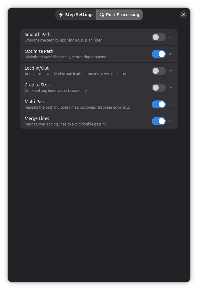
Contour operations support several post-processing options:
- Smooth Path - Reduce jagged edges in cutting paths
- Holding Tabs - Keep cut pieces attached to stock material
- Crop to Stock - Limit cuts to material boundary
- Path Optimization - Reduce travel distance between cuts
- Multi-Pass - Repeat cuts for thick materials
- Lead-In/Out - Add zero-power approach and exit moves for cleaner cut ends
Retracing with Custom Threshold
When working with bitmap images that have been converted to vectors, you can control which parts get traced:
- Override Threshold: Enable custom brightness threshold for tracing
- Threshold (0-255): Brightness cutoff value when override is enabled
- Lower values trace darker areas only
- Higher values include lighter areas
This is useful when the default tracing doesn't capture the detail level you need.
Remove Inner Paths
For designs with holes or internal cutouts, you can choose to trace only the outermost boundary:
- Remove Inner Paths: When enabled, only the outermost contour is traced
- Internal holes and cutouts are ignored
This is useful when you want to cut out a shape but preserve the interior, such as creating a frame or outline without cutting internal details.
Kerf Compensation
Kerf is the width of material removed by the laser beam:
Why it matters:
- A circle cut "on line" will be slightly smaller than designed
- The laser removes ~0.2-0.4mm of material (depending on beam width)
How to compensate:
- Measure your kerf on test cuts
- Use path offset = kerf/2
- For parts: offset inside by kerf/2
- For holes: offset outside by kerf/2
See Kerf for detailed guide.
Tips & Best Practices
Material Testing
Always test first:
- Cut small test shapes on scrap
- Start with conservative settings (lower power, slower speed)
- Gradually increase power or decrease speed
- Record successful settings
Cutting Order
Best practices:
- Engrave before cutting (keeps material secured)
- Cut inside features before outside perimeter
- Use holding tabs for parts that might move
- Cut smallest parts first (less vibration)
Troubleshooting
Cuts not going through material
- Increase: Power setting
- Decrease: Speed setting
- Add: More passes
- Check: Focus is correct
- Check: Beam is clean (dirty lens)
Excessive charring or burning
- Decrease: Power setting
- Increase: Speed setting
- Use: Air assist
- Try: Multiple faster passes instead of one slow
- Check: Material is appropriate for laser cutting
Parts fall out during cutting
- Add: Holding tabs
- Use: Cutting order optimization
- Cut: Inside features before outside
- Ensure: Material is flat and secured
Inconsistent cut depth
- Check: Material thickness is uniform
- Check: Material is flat (not warped)
- Check: Focus distance is consistent
- Verify: Laser power is stable
Missed corners or curves
- Decrease: Speed (especially on corners)
- Check: Machine acceleration settings
- Verify: Belts are tight
- Reduce: Path complexity (simplify curves)
Technical Details
Coordinate System
Contour operations work in:
- Units: Millimeters (mm)
- Origin: Depends on machine and job setup
- Coordinates: X/Y plane (Z for multi-pass depth)
Path Generation
Rayforge converts vector shapes to G-code:
- Offset path (if inside/outside cutting)
- Optimize path order (minimize travel)
- Add holding tabs (if configured)
- Generate G-code commands
G-code Commands
Typical contour G-code:
G0 X10 Y10          ; Rapid move to start
M3 S204             ; Laser on at 80% power
G1 X50 Y10 F500     ; Cut to point at 500 mm/min
G1 X50 Y50 F500     ; Cut to next point
G1 X10 Y50 F500     ; Continue cutting
G1 X10 Y10 F500     ; Complete the square
M5                  ; Laser off
Related Topics
- Engrave - Filling areas with engraving patterns
- Holding Tabs - Keeping parts secured during cutting
- Kerf - Improving cut accuracy
- Material Test Grid - Finding optimal power/speed settings