Camera Integration
Rayforge supports USB camera integration for precise material alignment and positioning. The camera overlay feature allows you to see exactly where your laser will cut or engrave on the material, eliminating guesswork and reducing material waste.
Setup Workflow
Setting up a camera follows four steps:
- Add a camera — Connect your camera and add it to the machine configuration
- Adjust image settings — Tune brightness, contrast, white balance, and noise reduction
- Calibrate the lens — Correct distortion with the calibration wizard or manual coefficients
- Align the camera — Map camera pixels to machine coordinates for accurate positioning
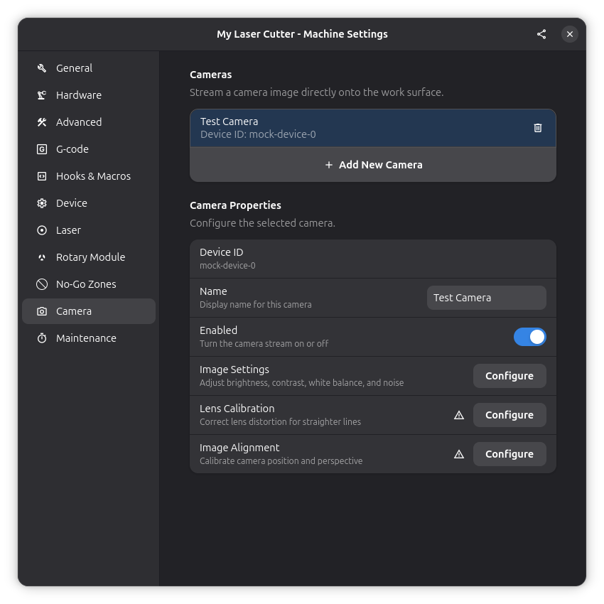
Steps 2–4 are accessed from the camera properties panel, where status icons show completion at a glance:
- ✓ Lens Calibration — Calibration has been performed
- ⚠ Image Alignment — Warning when alignment must be redone (e.g., after lens calibration)
- ✓ Image Alignment — Alignment is current and valid
Step 1: Add a Camera
Hardware Requirements
Compatible cameras:
- USB webcams (most common)
- Laptop built-in cameras (if running Rayforge on laptop near machine)
- Any camera supported by Video4Linux2 (V4L2) on Linux or DirectShow on Windows
Recommended setup:
- Camera mounted above the work area with clear view of material
- Consistent lighting conditions
- Camera positioned to capture the laser work area
- Secure mounting to prevent camera movement
Adding a Camera
-
Connect your camera to your computer via USB
-
Open Camera Settings:
- Navigate to Settings → Preferences → Camera
- Or use the camera toolbar button
-
Add a new camera:
- Click the + button to add a camera
- Enter a descriptive name (e.g., "Top Camera", "Work Area Cam")
- Select the device from the dropdown
- On Linux:
/dev/video0,/dev/video1, etc. - On Windows: Camera 0, Camera 1, etc.
- On Linux:
-
Enable the camera:
- Toggle the camera enable switch
- The live feed should appear on your canvas
Step 2: Adjust Image Settings
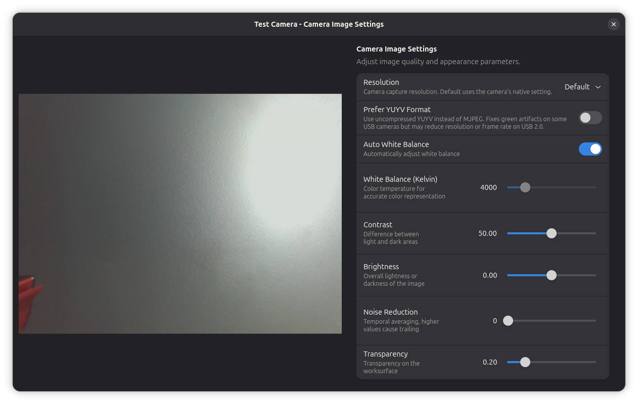
Click Configure next to Image Settings in the camera properties to open the image settings dialog. Adjust these parameters to get a clear camera view:
| Setting | Description |
|---|---|
| Brightness | Overall image brightness (-100 to +100) |
| Contrast | Edge definition and contrast (0 to 100) |
| Prefer YUYV | Use uncompressed YUYV instead of MJPEG. Slower but can fix some glitches |
| Transparency | Overlay opacity on canvas (0% opaque to 100% transparent) |
| White Balance | Color temperature correction (Auto or 2500–10000K) |
| Denoise | Temporal noise reduction (0.0 to 0.95) |
The YUYV option is useful if your camera produces green-tinted images with the default MJPEG format. Note that YUYV is uncompressed and may reduce the available resolution or frame rate on USB 2.0 connections.
Step 3: Lens Calibration
If your camera has a wide-angle lens or is mounted at an angle, the image may show visible curvature — straight lines appear bent, especially near the edges of the frame. This is called lens distortion, and it can throw off alignment even if your alignment points are carefully measured.
Rayforge includes a guided calibration wizard that corrects this distortion automatically. You can also adjust distortion coefficients manually.
Lens Calibration Dialog
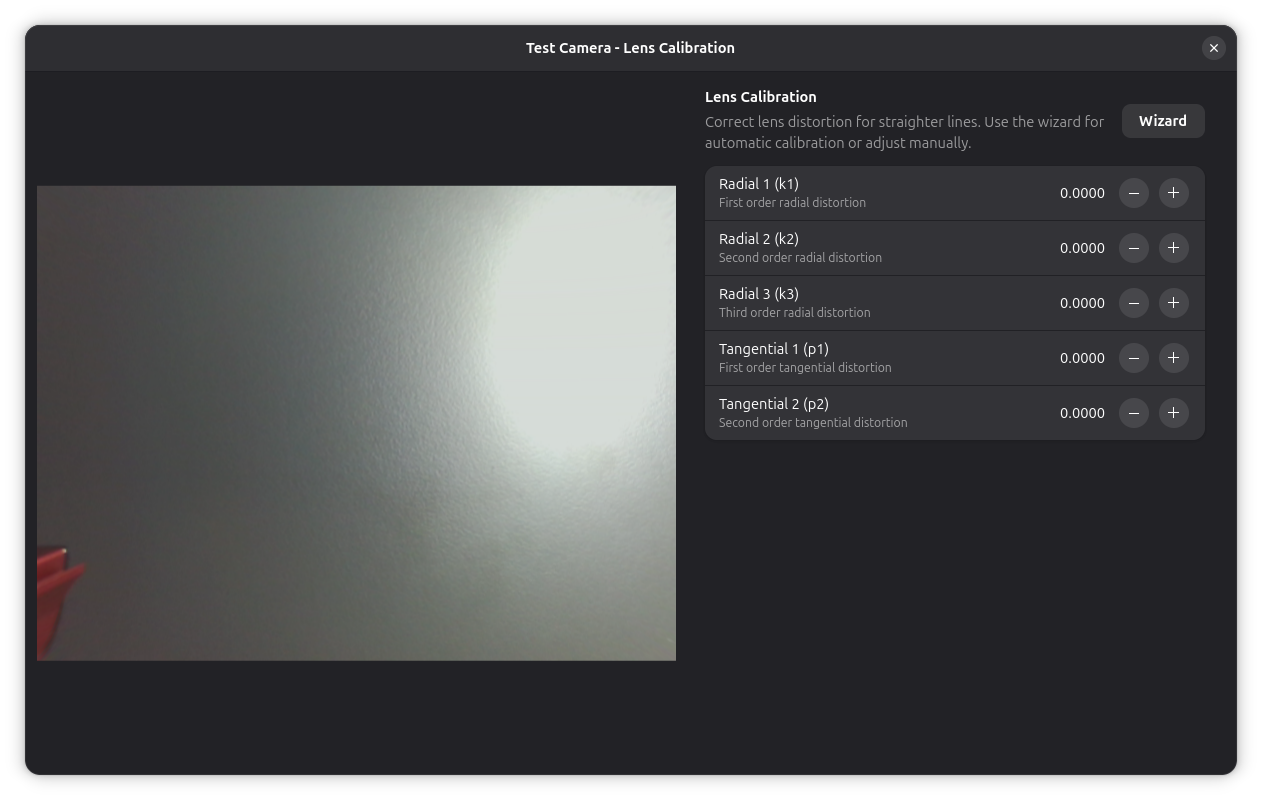
Open the lens calibration dialog by clicking Configure next to Lens Calibration in the camera properties. From here you can:
- Adjust distortion coefficients manually — Fine-tune radial (k1–k3) and tangential (p1–p2) distortion parameters
- Launch the calibration wizard — Click the Wizard button for guided automatic calibration
Manual adjustments are useful for fine-tuning after the wizard has computed an initial solution, or when you know the approximate distortion values for your lens.
Calibration Wizard
The calibration wizard walks you through capturing several images of a printed calibration card from different positions on the bed. It then computes a distortion model automatically.
Step 1: Configure the calibration card
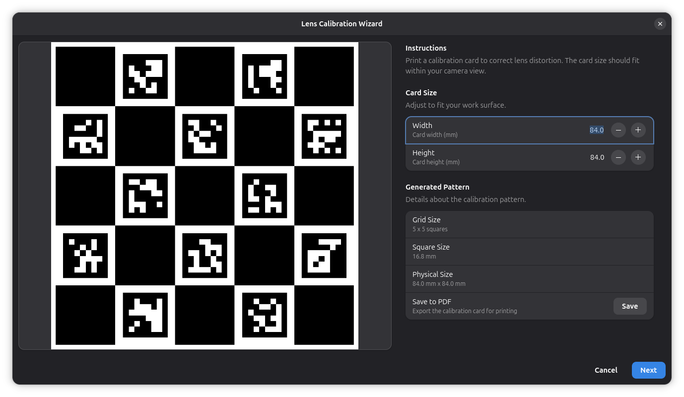
- Click Wizard in the lens calibration dialog to start
- Set the Width and Height of your printed card
- The preview updates in real-time — the card should cover about 70% of the camera view
- Click Save to PDF to export the card for printing
- Print the card and place it on the laser bed
Step 2: Capture frames
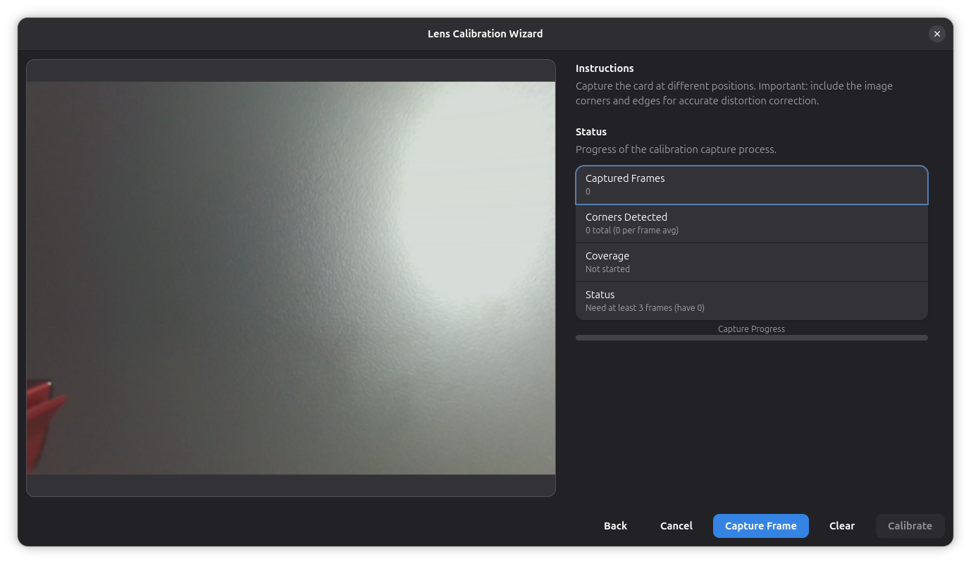
- Click Next to enter capture mode
- Position the calibration card at different locations and angles within the camera view
- Click Capture Frame for each position
- Aim for at least 8 captures covering the entire frame, including corners and edges
- The progress bar and status indicators show capture quality
Step 3: Apply calibration
- Once enough frames are captured, click Calibrate
- The computed distortion coefficients are automatically applied to the camera
- The camera overlay now shows a corrected, straight image
Step 4: Image Alignment
Camera alignment calibrates the relationship between camera pixels and real- world coordinates, enabling accurate positioning.
Why Alignment is Necessary
The camera sees the work area from above, but the image may be:
- Rotated relative to the machine axes
- Scaled differently in X and Y directions
- Distorted by lens perspective
Alignment creates a transformation matrix that maps camera pixels to machine coordinates.
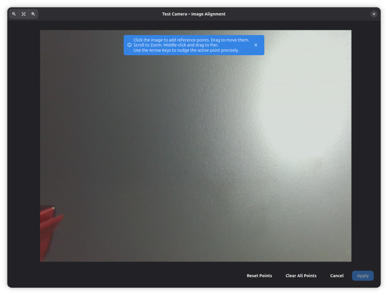
Alignment Procedure
-
Open the Alignment Dialog:
- Click the Configure button next to Image Alignment in the camera properties
- The dialog shows the camera feed with the current alignment overlay
-
Place alignment markers:
- You need at least 3 reference points (4 recommended for better accuracy)
- Alignment points should be spread across the work area
- Use known positions like:
- Machine home position
- Ruler markings
- Pre-cut alignment holes
- Calibration grid
-
Mark image points:
- Click on the camera image to place a point at a known location
- The bubble widget appears showing point coordinates
- Repeat for each reference point
-
Enter world coordinates:
- For each image point, enter the real-world X/Y coordinates in mm
- These are the actual machine coordinates where each point is located
- Measure accurately with a ruler or use known machine positions
-
Apply alignment:
- Click Apply to calculate the transformation
- The camera overlay will now be properly aligned
-
Verify alignment:
- Move the laser head to a known position
- Check that the laser dot aligns with the expected position in the camera view
- Fine-tune by re-aligning if needed
Alignment Status
The camera properties panel shows the alignment status with an icon:
- Checkmark — Alignment is current and valid
- Warning — Alignment must be redone. This happens when lens calibration is updated, because the distortion correction changes the camera image and invalidates the existing alignment. Your alignment points are preserved — simply open the dialog and click Apply again.
Example Workflow
- Move laser to home position (0, 0) and mark in camera
- Move laser to (100, 0) and mark in camera
- Move laser to (100, 100) and mark in camera
- Move laser to (0, 100) and mark in camera
- Enter exact coordinates for each point
- Click Apply and verify
- Use points at the corners of your work area for maximum coverage
- Avoid clustering points in one area
- Measure world coordinates carefully — accuracy here determines overall alignment quality
- Re-align if you move the camera or change the focus distance
- Re-align after updating lens calibration
- Save your alignment — it persists across sessions
Using the Camera Overlay
Once aligned, the camera overlay helps position jobs accurately. Toggle it by clicking the camera icon in the main window toolbar.
Multiple Cameras
Rayforge supports multiple cameras for different views or machines:
- Add multiple cameras in preferences
- Each camera can have independent alignment
- Switch between cameras using the camera selector
- Use cases:
- Top view + side view for 3D objects
- Different cameras for different machines
- Wide angle + detail camera
Troubleshooting
Camera Not Detected
Problem: Camera doesn't appear in device list.
Solutions:
Linux: Check if the camera is recognized by the system:
# List video devices
ls -l /dev/video*

# Check camera with v4l2
v4l2-ctl --list-devices

# Test with another application
cheese  # or VLC, etc.
For Snap users:
# Grant camera access
sudo snap connect rayforge:camera
Windows:
- Check Device Manager for camera under "Cameras" or "Imaging devices"
- Ensure no other application is using the camera (close Zoom, Skype, etc.)
- Try a different USB port
- Update camera drivers
Camera Shows Black Screen
Problem: Camera detected but shows no image.
Possible causes:
- Camera in use by another application — Close other video apps
- Incorrect device selected — Try different device IDs
- Camera permissions — On Linux Snap, ensure camera interface connected
- Hardware issue — Test camera with another application
Solutions:
# Linux: Release camera device
sudo killall cheese  # or other camera apps

# Check which process is using the camera
sudo lsof /dev/video0
Alignment Not Accurate
Problem: Camera overlay doesn't match real laser position.
Diagnosis:
- Insufficient alignment points — Use at least 4 points
- Measurement errors — Double-check world coordinates
- Camera moved — Re-align if camera position changed
- Non-linear distortion — May need lens calibration
Improve accuracy:
- Use more alignment points (6–8 for very large areas)
- Spread points across entire work area
- Measure world coordinates very carefully
- Use machine movement commands to precisely position laser at known coordinates
- Re-align after any camera adjustments
Poor Image Quality
Problem: Camera image is blurry, dark, or washed out.
Solutions:
- Adjust brightness/contrast in camera settings
- Improve lighting — Add consistent work area lighting
- Clean camera lens — Dust and debris reduce clarity
- Check focus — Auto-focus may not work well; use manual if possible
- Reduce transparency temporarily to see camera image more clearly
- Try different white balance settings
- Adjust denoise setting if image appears grainy
Camera Lag or Stuttering
Problem: Live camera feed is choppy or delayed.
Solutions:
- Lower camera resolution in device settings (if accessible)
- Close other applications using CPU/GPU
- Update graphics drivers
Related Pages
- 3D Preview — Preview execution with camera overlay
- Framing Jobs — Verify job position
- General Settings — Machine configuration