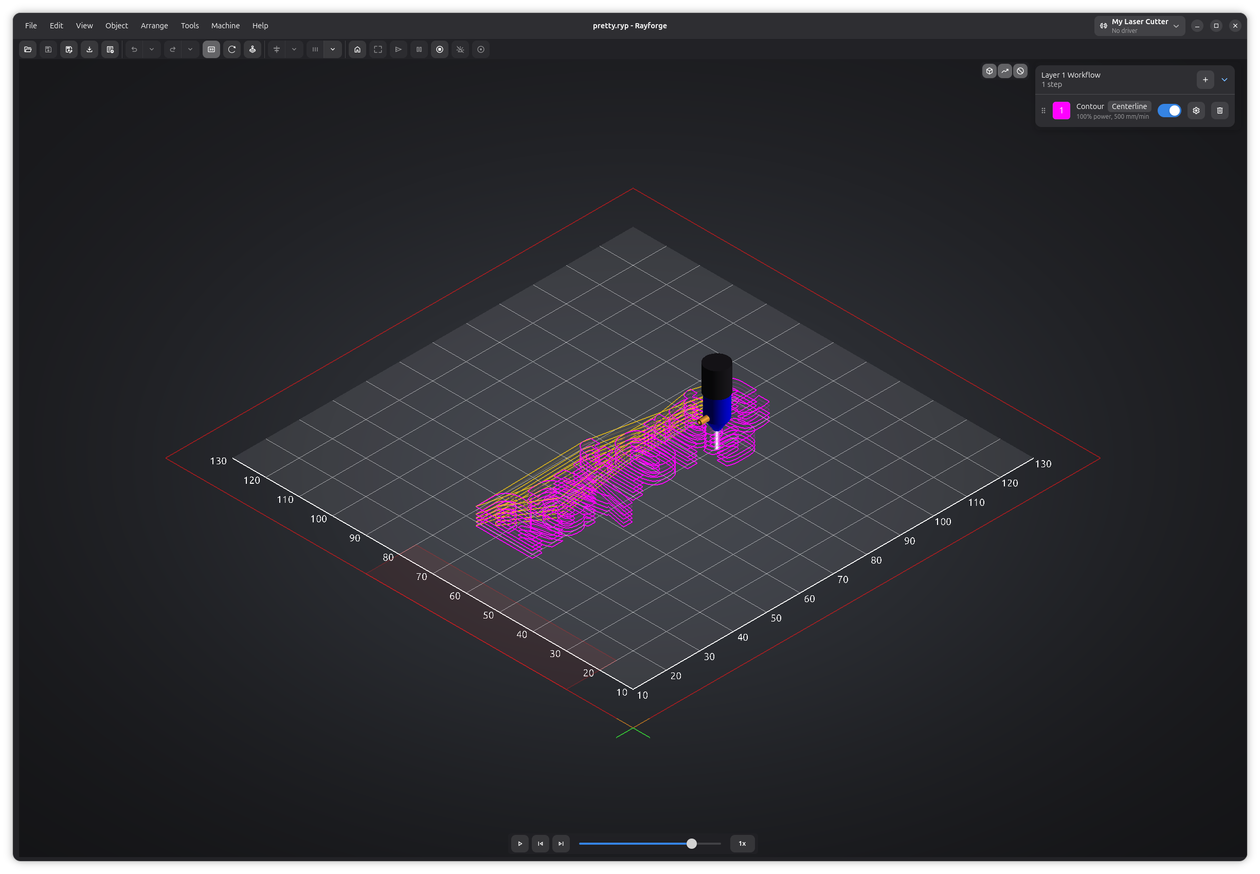
3D View
The 3D view lets you visualize your G-code toolpaths and simulate job execution before sending them to your machine.
Opening 3D View
Access the 3D view:
- Menu: View → 3D View
- Keyboard: F12
Navigation
Mouse Controls
- Rotate: Left-click and drag (Z-axis), middle-click and drag (3-axis orbit)
- Pan: shift + middle-click and drag
- Zoom: Scroll wheel
View Presets
Quick camera angles:
- Top (1): Bird's eye view
- Front (2): Front elevation
- Right (3): Right side view
- Left (4): Left side view
- Back (5): Back elevation
- Isometric (7): 3D isometric view
Work Coordinate System Display
The 3D view visualizes the active Work Coordinate System (WCS) differently from the 2D canvas:
Grid and Axes
- Isolated display: The grid and axes appear as if the WCS origin is the world origin
- Offset applied: The entire grid is shifted to align with the selected WCS offset
- Labels relative to WCS: Coordinate labels show positions relative to the WCS origin, not machine origin
This "in isolation" display makes it easy to understand where your job will run relative to the selected work coordinate system, without being confused by the machine's absolute position.
Changing WCS
The 3D view automatically updates when you change the active WCS:
- Select a different WCS from the toolbar dropdown
- The grid and axes shift to reflect the new WCS origin
- Labels update to show coordinates relative to the new WCS
The 3D view shows your toolpaths relative to the selected WCS. When you change WCS, you'll see the toolpaths appear to move because the reference point (the grid) has changed, not because the toolpaths themselves moved.
Display Options
Visibility toggles are located as overlay buttons at the top-right of the 3D canvas:
- Model: Toggle the 3D machine model visibility
- Travel moves: Toggle rapid travel move visibility
- No-go zones: Toggle no-go zone visibility
Toolpath Visualization
Customize what you see:
- Show Rapid Moves: Display travel moves (dotted lines)
- Show Work Moves: Display cutting/engraving moves (solid lines)
- Color by Operation: Different colors for each operation
When using machines with multiple laser heads, each laser can have its own cut and raster colors configured in Laser Settings. This makes it easy to identify which laser will perform each operation.
Laser Head Model
The 3D view renders a model of your laser head that moves along the toolpath during simulation. You can assign a 3D model to each laser head in the Laser Settings page of Machine Settings. The model's scale, rotation, and focal distance can be adjusted to match your physical setup.
During simulation, a glowing laser beam is drawn from the head downward when the laser is active.
Simulation
The 3D view includes a built-in simulator with playback controls overlaid at the bottom of the canvas.
Playback Controls
- Play/Pause (space): Animate toolpath execution
- Step Forward/Back: Advance or rewind by one operation at a time
- Speed: Cycle through playback speeds (1x, 2x, 4x, 8x, 16x)
- Timeline slider: Drag to scrub through the job
Synchronized G-code View
The simulation stays in sync with the G-code viewer in the bottom panel. Stepping through the simulation highlights the corresponding line in the G-code viewer, and clicking a line in the G-code viewer jumps the simulation to that point.
Layer Visibility
Toggle visibility of individual layers:
- Click a layer name to show or hide it
- Focus on specific layers for inspection
Verification Checklist
Before sending to machine, verify:
- Toolpath is complete with no missing segments
- Engrave operations run before cuts
- Job starts at the expected position
- Holding tabs are in the correct locations
Some additional checks are performed automatically. When you run or export a job, Rayforge runs sanity checks that verify machine extents, workarea boundaries, and no-go zone collisions.
Performance Tips
For large or complex jobs:
- Hide rapid moves to focus on work moves only
- Reduce the number of visible layers
- Close other applications to free up GPU resources
Troubleshooting
Preview is blank or black
- Check that operations are enabled
- Verify objects have operations assigned
Slow or laggy preview
- Hide rapid moves
- Hide 3D models
- Reduce the number of visible layers
Related Pages:
- Work Coordinate Systems - WCS
- Main Window - Main interface overview
- Settings - Application preferences