


Parametric 2D Sketcher
Rayforge includes a parametric 2D sketcher for drawing parts directly in the application. Instead of importing finished artwork from another program, you sketch lines, curves, and shapes on an infinite canvas and tie them together with constraints. The result is a design that stays precise no matter how often you change your mind about its dimensions.
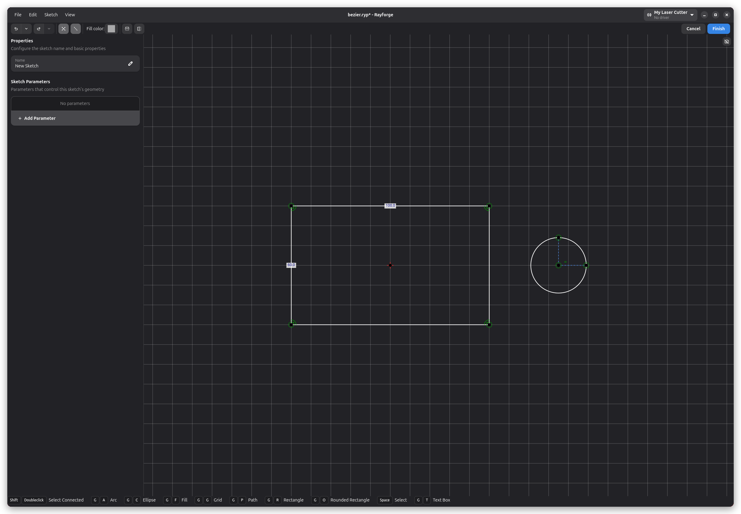
What "parametric" means here
A sketch is more than a drawing — it is a small model with rules. The rules are constraints: statements like "these two lines are parallel", "this corner is a right angle", or "this edge is exactly 100 mm long". After every change, a solver re-arranges the geometry so that all rules hold again.
This has a practical consequence: you can capture your design intent once and then keep editing.
Raise the distance constraint from 100 mm to 130 mm and the whole part follows. Dimensional
constraints accept expressions, too — a radius of width/2 stays half the width, whatever the width
becomes.
When every remaining degree of freedom is pinned down by a constraint, the sketch is fully constrained. The editor tells you where you stand through colors: geometry that is held by constraints is drawn in green, unconstrained points in black, and once a sketch is fully constrained the green turns darker. Constraints that contradict each other are marked in red and listed in the conflicts panel in the sidebar, where you can inspect or delete them.

An under-constrained sketch is not a mistake — it is often exactly what you want while experimenting. The Constraints page explains every available constraint type in detail.
The sketch editor
Sketches live in the document like any other workpiece. Create one with the New Sketch button in the bottom panel (or right-click the canvas and pick the same entry from the context menu), and the sketch editor takes over the window: the canvas in the middle, a properties panel with the sketch name and its parameters on the left, and a toolbar on top.
The toolbar collects the session-level tools — undo and redo, toggles for constraint and construction-geometry visibility, fill and line colors, mirroring — and the Finish and Cancel buttons. Finish saves the sketch back into the document; Cancel discards the changes made in this session. To re-edit an existing sketch later, double-click it in the main workspace, or select it and choose Edit Sketch from the context menu.
The editor is keyboard-first. The status bar at the bottom always lists the shortcuts that apply to the current tool and selection, so the relevant keys are on screen exactly when you need them. Full undo and redo is available for every operation.
The pie menu
Right-clicking anywhere in the sketch editor opens the pie menu — a radial menu that puts every drawing and modification tool one click away. The menu is context-aware: right-clicking empty space offers the drawing tools, while right-clicking a selected line offers the constraints and modifications that make sense for a line. Related tools are collapsed into groups; hover a group to fan out its children. Right-click again to close the menu or re-open it somewhere else.

Keyboard shortcuts
The sketcher is operated from the keyboard, and the status bar at the bottom always lists the shortcuts that apply to the current tool and selection. These general shortcuts work everywhere in the editor:
| Action | Shortcut |
|---|---|
| Select tool | Space |
| Undo / Redo | Ctrl+Z / Ctrl+Y (Ctrl+Shift+Z) |
| Duplicate selection | Ctrl+D |
| Delete selection | Delete |
| Nudge selection | Arrow keys (Shift: larger) |
| Mirror selection vertically / horizontally | M+V / M+H |
| Toggle construction mode | G+N |
| Cancel operation or deselect | Escape |
| Fit view to content | 1 |
Mirroring operates in-place across the selection's bounding-box center; constraints that span the selection boundary are dropped, internal constraints are preserved. Duplicates get fresh IDs and remapped internal constraints; undo removes them.
Each drawing and modification tool additionally has a two-key shortcut, documented on its page:
| Tool | Shortcut |
|---|---|
| Path | G+P |
| Arc | G+A |
| Ellipse | G+C |
| Rectangle | G+R |
| Rounded Rectangle | G+O |
| Fill Area | G+F |
| Text Box | G+T |
| Circular Array | G+Y |
| Array Along Curve | G+W |
| Grid | G+G |
| Offset | O+F |
| Chamfer | C+H |
| Fillet | C+F |
The constraint shortcuts are listed on the Constraints page.
Grid and snapping
The canvas shows an adaptive grid whose spacing adjusts to the zoom level and is labeled along the axes in your preferred units, so it doubles as a ruler: you can read sizes and positions straight off the canvas.
While you draw or drag, magnetic snapping pulls the cursor toward nearby reference points. The canvas marks what the cursor is attracted to:
- a blue circle marks an existing point (endpoint),
- green arrows mark a midpoint,
- a pink highlight means the cursor is over an edge,
- dashed lines across the canvas are alignment guides, shown when the cursor lines up horizontally or vertically with another point,
- further indicators cover special cases such as equidistant spacings (orange), tangency (purple), and centers (red).
Snapping is not just visual aid — committing geometry onto a snap target creates the matching
constraint automatically. Finishing a line on an existing endpoint makes the two coincident;
snapping to a midpoint creates a symmetry constraint; alignment guides become horizontal or vertical
constraints. If you prefer free placement, Tab toggles magnetic snapping off. Holding Shift
while dragging constrains movement to the nearest axis.

Construction geometry
Any entity can be flagged as construction geometry. Construction entities are drawn dashed, act as
layout guides for the solver like any other geometry, and are excluded from the toolpaths when the
sketch is manufactured. They are handy for center lines, construction circles, and the scaffolding
behind symmetrical designs. Select one or more entities and press G+N (or use the Construction
entry in the pie menu) to toggle the flag; the construction toggle in the toolbar hides them when
they get in the way.
Where to go next
The drawing tools are each documented on their own page: Path (lines and bezier curves), Arc and Ellipse, Rectangle (and rounded rectangles), Fill Areas, Text Box, and Grid. Modifications such as Offset and Chamfer and Fillet reshape existing geometry, Arrays copies it along a circle or a curve, and Parameters and Expressions explains how to add and edit parameters, drive geometry and text boxes with them, and assign values per sketch instance. Sketches can be saved and re-imported with all constraints intact — see Import and Export.