Print & Cut
Align laser cuts to pre-printed material by registering reference points on your design and matching them to their physical positions on the material. This is useful for cutting stickers, labels, or anything that needs to line up with an existing print.
Prerequisites
The addon requires a configured machine. Your machine must be connected for the jogging step. You also need one workpiece or group selected on the canvas.
Opening the Wizard
Select a single workpiece or group on the canvas, then open Tools - Align to Physical Position. The wizard opens as a three-step dialog with a preview of your workpiece on the left and controls on the right.
Step 1: Pick Design Points
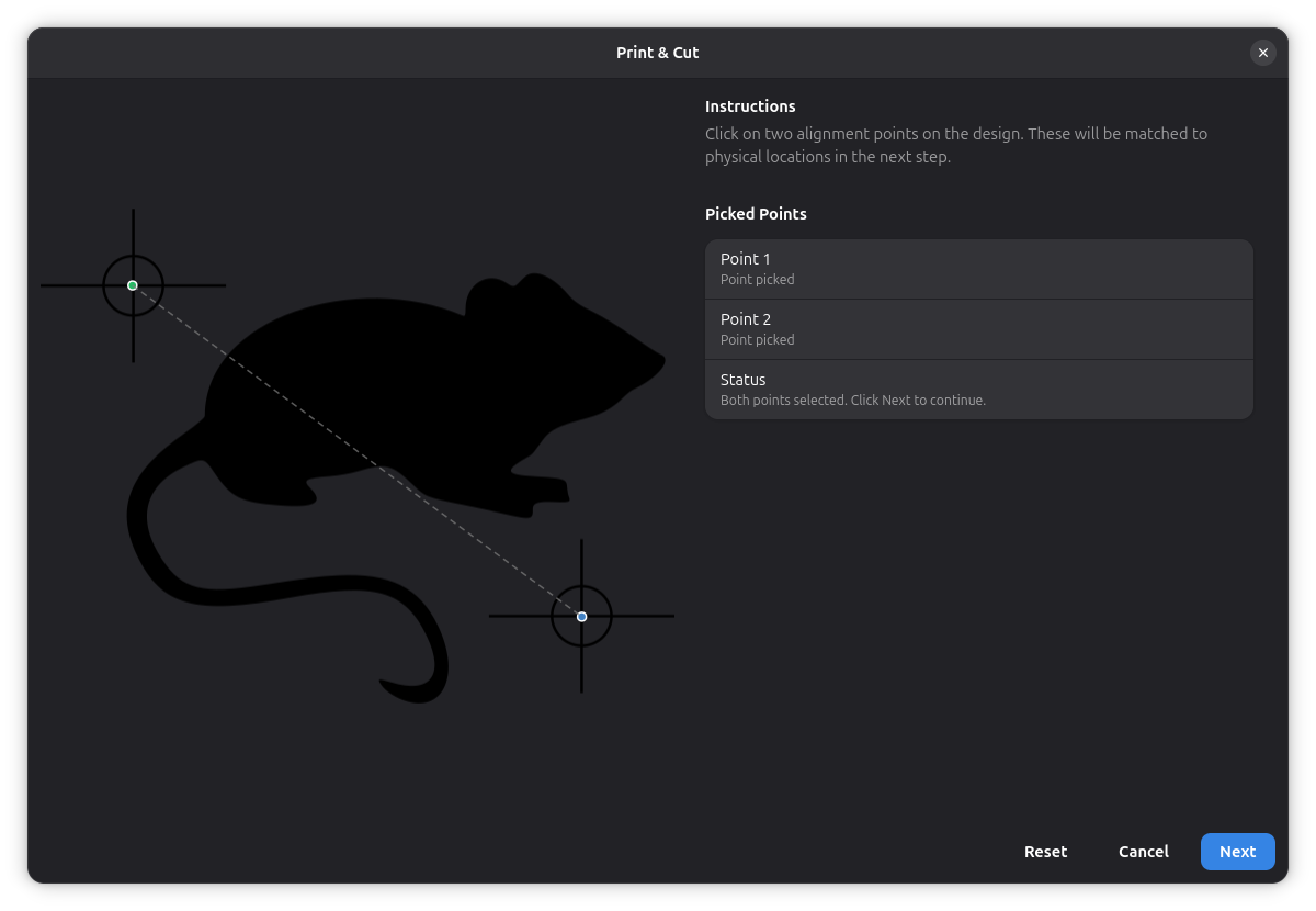
The left panel shows a rendering of your selected workpiece. Click directly on the rendered image to place the first alignment point, marked in green, then click again to place the second point, marked in blue. A dashed line connects the two points.
Choose two points that correspond to identifiable features on your physical material — for example, printed registration marks or distinct corners. The points need to be far enough apart for accurate alignment. You can drag either point after placing it to fine-tune the position.
Use the scroll wheel to zoom in on the preview, and middle-click drag to pan around. The Reset button at the bottom clears both points and lets you start over.
Once both points are placed, click Next to continue.
Step 2: Record Physical Positions
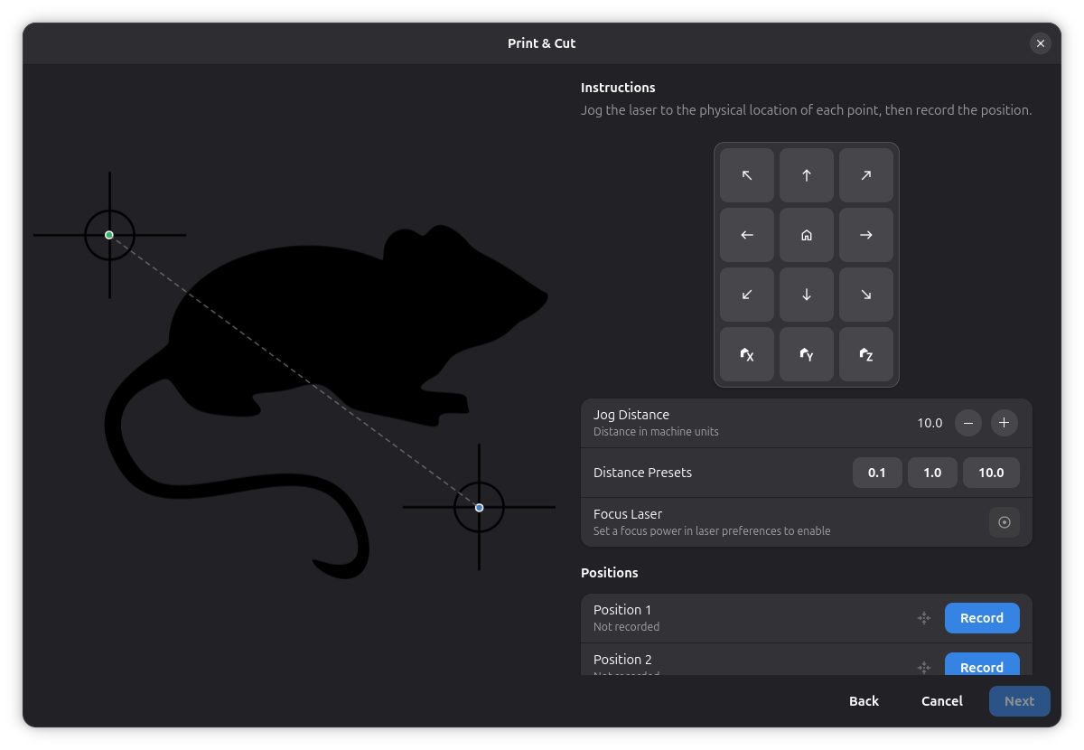
On this page you jog the laser to the physical locations that correspond to the two design points you picked. The right panel shows a directional pad for jogging and a distance control that sets how far the laser moves per step.
Jog the laser to the physical location matching your first design point, then click Record next to Position 1. The recorded coordinates appear in the row. Repeat the process for Position 2. You can revisit a recorded position at any time by clicking the Go-To button next to it.
The Focus Laser toggle turns the laser on at your configured focus power, which creates a visible dot on the material to help you locate positions precisely. This toggle requires a focus power value greater than zero in your laser settings.
The current laser position is shown at the bottom of the panel. When both positions are recorded, click Next to proceed.
Step 3: Review and Apply the Transform
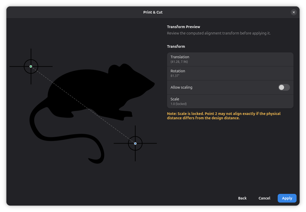
The final page shows the computed alignment as a translation offset and a rotation angle. These values are derived from the difference between your design points and the physical positions you recorded.
By default, scaling is locked at 1.0. If your physical material differs in size from the design — for example, due to printer scaling — enable the Allow scaling toggle. The scale factor is then computed from the ratio of the physical distance to the design distance between your two points. A note appears when scaling is locked but the distances do not match, indicating that the second point may not align exactly.
Click Apply to move and rotate the workpiece on the canvas to match the physical positions. The transform is applied as an undoable action.
Related Topics
- Workpiece Positioning - Position and transform workpieces manually
- Laser Settings - Configure focus power for the laser