Material Test Grid
The Material Test Grid generator creates parametric test patterns to help you find optimal laser settings for different materials.
Overview
Material testing is essential for laser work - different materials require different power and speed settings. The Material Test Grid automates this process by:
- Generating test grids with configurable speed/power ranges
- Providing presets for common laser types (Diode, CO2)
- Optimizing execution order for safety (fastest speeds first)
- Adding labels to identify each test cell's settings
Creating a Material Test Grid�
Step 1: Open the Generator
Access the Material Test Grid generator:
- Menu: Tools → Material Test Grid
- This creates a special workpiece that generates the test pattern
Step 2: Choose a Preset (Optional)
Rayforge includes presets for common scenarios:
| Preset | Speed Range | Power Range | Use For |
|---|---|---|---|
| Diode Engrave | 1000-10000 mm/min | 10-100% | Diode laser engraving |
| Diode Cut | 100-5000 mm/min | 50-100% | Diode laser cutting |
| CO2 Engrave | 3000-20000 mm/min | 10-50% | CO2 laser engraving |
| CO2 Cut | 1000-20000 mm/min | 30-100% | CO2 laser cutting |
Presets are starting points - you can adjust all parameters after selecting one.
Step 3: Configure Parameters
Adjust the test grid parameters in the settings dialog:
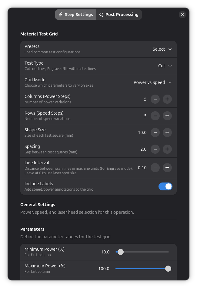
Test Type
- Engrave: Fills squares with raster pattern
- Cut: Cuts outline of squares
Speed Range
- Min Speed: Slowest speed to test (mm/min)
- Max Speed: Fastest speed to test (mm/min)
- Columns in grid represent different speeds
Power Range
- Min Power: Lowest power to test (%)
- Max Power: Highest power to test (%)
- Rows in grid represent different power levels
Grid Dimensions
- Columns: Number of speed variations (typically 3-7)
- Rows: Number of power variations (typically 3-7)
Size & Spacing
- Shape Size: Size of each test square in mm (default: 20mm)
- Spacing: Gap between squares in mm (default: 5mm)
Labels
- Include Labels: Enable/disable axis labels showing speed and power values
- Labels appear on left and top edges
- Label Power (%): Power setting for engraving labels
- Label Speed (mm/min): Speed for engraving labels (default: 1000 mm/min)
Labels are engraved first, before the test grid, so they are not obscured by the test pattern.
Line Interval (Engrave Test Only)
- Line Interval (mm): Spacing between scan lines when using the engrave test type
- Smaller values create denser fills but take longer to execute
- Typical values: 0.1-0.3mm
Step 4: Generate the Grid
Click Generate to create the test pattern. The grid appears on your canvas as a special workpiece.
Understanding the Grid Layout
Grid Organization
Power (%)     Speed (mm/min) →
    ↓      1000   2500   5000   7500   10000
  100%     [  ]   [  ]   [  ]   [  ]   [  ]
   75%     [  ]   [  ]   [  ]   [  ]   [  ]
   50%     [  ]   [  ]   [  ]   [  ]   [  ]
   25%     [  ]   [  ]   [  ]   [  ]   [  ]
   10%     [  ]   [  ]   [  ]   [  ]   [  ]
- Columns: Speed increases from left to right
- Rows: Power increases from bottom to top
- Labels: Show exact values for each row/column
Grid Size Calculation
Without labels:
- Width = columns × (shape_size + spacing) - spacing
- Height = rows × (shape_size + spacing) - spacing
With labels:
- Add 15mm margin to left and top for label space
Example: 5×5 grid with 20mm squares and 5mm spacing:
- Without labels: 120mm × 120mm
- With labels: 135mm × 135mm
Execution Order (Risk Optimization)
Rayforge executes test cells in a risk-optimized order to prevent material damage:
- Highest speed first: Fast speeds are safer (less heat buildup)
- Lowest power within speed: Minimizes risk at each speed level
This prevents charring or fire from starting with slow, high-power combinations.
Example execution order for 3×3 grid:
Order:  1  2  3
        4  5  6  ← Highest speed, power increasing
        7  8  9

(Fastest speed/lowest power executed first)
Using Material Test Results
Step 1: Run the Test
- Load your material in the laser
- Focus the laser properly
- Run the material test grid job
- Monitor the test - stop if any cell causes problems
Step 2: Evaluate Results
After the test completes, examine each cell:
- Too light: Increase power or decrease speed
- Too dark/charred: Decrease power or increase speed
- Perfect: Note the speed/power combination
Step 3: Record Settings
Document your successful settings for future reference:
- Material type and thickness
- Operation type (engrave or cut)
- Speed and power combination
- Number of passes
- Any special notes
Consider creating a reference document with your material test results for quick lookup in future projects.
Advanced Usage
Combining with Other Operations
Material test grids are regular workpieces - you can combine them with other operations:
Example workflow:
- Create material test grid
- Add contour cut around the entire grid
- Run test, cut free, evaluate results
This is useful for cutting the test piece free from stock material.
Custom Test Ranges
For fine-tuning, create narrow-range tests:
Coarse test (find ballpark):
- Speed: 1000-10000 mm/min (5 columns)
- Power: 10-100% (5 rows)
Fine test (optimize):
- Speed: 4000-6000 mm/min (5 columns)
- Power: 35-45% (5 rows)
Different Materials, Same Grid
Run the same grid configuration on different materials to build your material library faster.
Tips & Best Practices
Grid Design
✅ Start with presets - Good starting points for common scenarios ✅ Use 5×5 grids - Good balance of detail and test time ✅ Enable labels - Essential for identifying results ✅ Keep squares ≥20mm - Easier to see and measure results
Testing Strategy
✅ Test scrap first - Never test on final material ✅ One variable at a time - Test speed OR power range, not both extremes ✅ Allow cooldown - Wait between tests on same material ✅ Consistent focus - Same focus distance for all tests
Safety
⚠️ Monitor tests - Never leave running tests unattended ⚠️ Start conservative - Begin with lower power ranges ⚠️ Check ventilation - Ensure proper fume extraction ⚠️ Fire watch - Have fire extinguisher ready
Troubleshooting
Test cells execute in wrong order
- Rayforge uses risk-optimized order (fastest speeds first)
- This is intentional and cannot be changed
- See Execution Order above
Results are inconsistent
- Check: Material is flat and properly secured
- Check: Focus is consistent across entire test area
- Check: Laser power is stable (check power supply)
- Try: Smaller grid to reduce test area
Related Topics
- 3D Preview - Preview test execution before running
- Engrave - Understanding engrave operations
- Contour Cutting - Understanding cut operations