Frame Outline
Frame Outline creates a simple rectangular cutting path around your entire design. It's the quickest way to add a clean border or cut your work free from the material sheet.
Overview
Frame Outline operations:
- Create a rectangular boundary around all content
- Add configurable offset/margin from the design
- Support kerf compensation for accurate sizing
- Work with any combination of objects on the canvas
When to Use Frame Outline
Use frame outline for:
- Adding a decorative border around your design
- Cutting your work free from the material sheet
- Creating a simple rectangular boundary
- Quick framing without complex path calculations
Don't use frame outline for:
- Irregular shapes around multiple objects (use Shrink Wrap instead)
- Cutting individual parts (use Contour instead)
- Following the exact shape of your design
Creating a Frame Outline Operation
Step 1: Arrange Your Design
- Place all objects on the canvas
- Position them where you want them relative to the frame
- The frame will be calculated around the bounding box of all content
Step 2: Add Frame Outline Operation
- Menu: Operations → Add Frame Outline
- Right-click: Context menu → Add Operation → Frame Outline
Step 3: Configure Settings
Configure the frame parameters:
- Power & Speed: Match your material's cutting requirements
- Offset: Distance from content edge to frame
- Path Offset: Inside, outside, or centerline cutting
Key Settings
Power & Speed
Power (%):
- Laser intensity for cutting the frame
- Match your material's cutting requirements
Speed (mm/min):
- How fast the laser moves
- Slower for thicker materials
Passes:
- Number of times to cut the frame
- Usually 1-2 passes
- Add passes for thicker materials
Offset Distance
Offset (mm):
- Distance from the design's bounding box to the frame
- Creates a margin/border around your work
Typical values:
- 0mm: Frame touches the design edge
- 2-5mm: Small margin for clean appearance
- 10mm+: Large border for mounting or handling
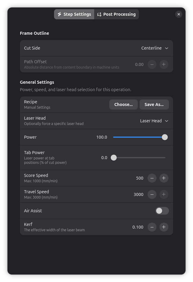
Path Offset (Cut Side)
Controls where the laser cuts relative to the frame path:
| Cut Side | Description | Use For |
|---|---|---|
| Centerline | Cuts directly on the path | Standard cutting |
| Outside | Cuts outside the frame path | Making the frame slightly larger |
| Inside | Cuts inside the frame path | Making the frame slightly smaller |
Kerf Compensation
Frame outline supports kerf compensation:
- Automatically adjusts for laser beam width
- Ensures accurate final dimensions
- Uses the kerf value from your laser head settings
Post-Processing
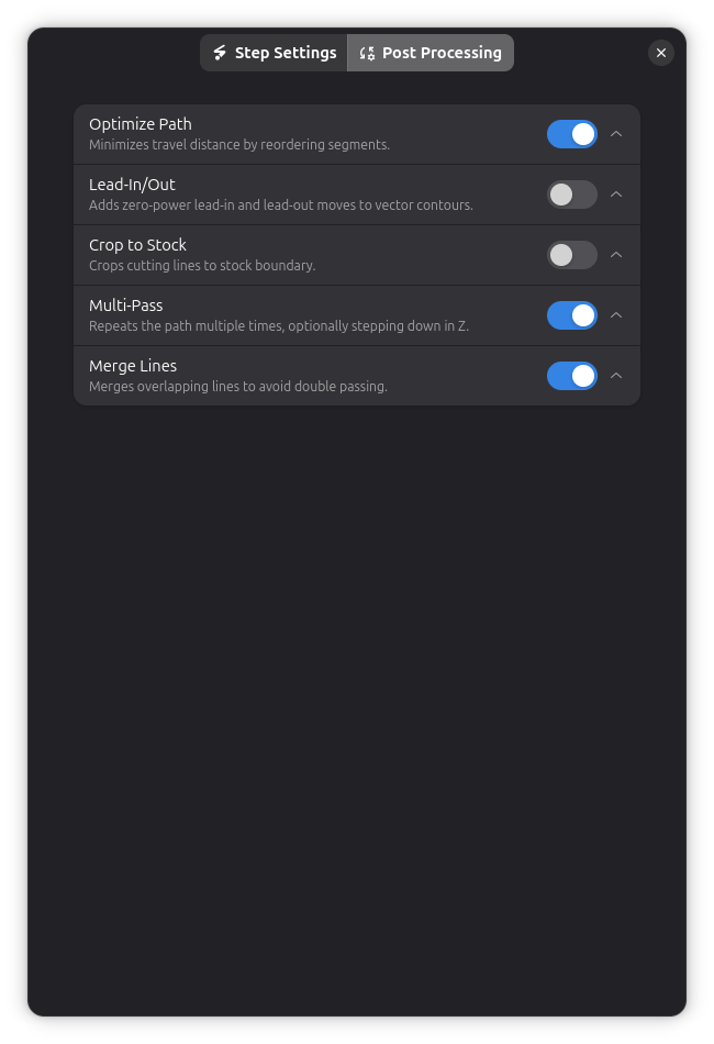
Frame Outline operations support several post-processing options:
- Holding Tabs - Keep the framed piece attached to stock
- Crop to Stock - Limit cuts to material boundary
- Path Optimization - Reduce travel distance
- Multi-Pass - Repeat cuts for thick materials
- Lead-In/Out - Add zero-power approach and exit moves for cleaner cut ends
Use Cases
Decorative Border
Scenario: Add a clean rectangular border around a plaque or sign
Process:
- Design your content (text, logos, etc.)
- Add Frame Outline with 3-5mm offset
- Cut at decorative scoring settings (low power)
Result: Professional-looking bordered piece
Cut Free from Sheet
Scenario: Remove your finished work from the material sheet
Process:
- Complete all other operations (engrave, contour cuts)
- Add Frame Outline as the last operation
- Set offset to include a small margin
Benefits:
- Clean separation from sheet
- Consistent edge quality
- Easy to execute as final step
Batch Processing Boundary
Scenario: Create a cutting boundary for multiple nested parts
Process:
- Arrange all parts on the canvas
- Add individual contour operations for parts
- Add Frame Outline around everything
- Frame cuts last (in separate layer)
Order: Engrave → Part contours → Frame outline
Tips & Best Practices
Layer Order
Best practice:
- Place Frame Outline in its own layer
- Execute frame as the last operation
- This ensures all other work completes first
Why last?
- Material stays secured during other operations
- Prevents pieces from shifting
- Cleaner final result
Offset Selection
Choosing offset:
- 0-2mm: Tight fit, minimal material waste
- 3-5mm: Standard margin, looks professional
- 10mm+: Extra material for handling/mounting
Consider:
- Final use of the piece
- Whether edges will be visible
- Material cost and availability
Quality Settings
For clean frame cuts:
- Use air assist
- Ensure proper focus
- Multiple faster passes often better than one slow pass
- Keep material flat and secured
Combining with Other Operations
Frame + Engrave + Contour
Typical workflow for a finished piece:
- Layer 1: Engrave details (text, images)
- Layer 2: Contour cut individual parts
- Layer 3: Frame outline (cut free)
Execution order ensures:
- Engraving happens while material is flat and secured
- Part details are cut before final separation
- Frame cuts everything free at the end
Frame vs Shrink Wrap
| Feature | Frame Outline | Shrink Wrap |
|---|---|---|
| Shape | Always rectangular | Follows object contours |
| Speed | Very fast (4 lines) | Depends on complexity |
| Use case | Simple borders, cutting free | Efficient material use |
| Flexibility | Fixed rectangle | Adapts to design |
Choose Frame Outline when:
- You want a rectangular border
- Simplicity is preferred
- Cutting free from sheet
Choose Shrink Wrap when:
- You want to minimize material waste
- Design has irregular shape
- Efficiency is important
Troubleshooting
Frame is too tight/loose
- Adjust: Offset distance setting
- Check: Path offset (inside/outside/centerline)
- Verify: Kerf compensation is correct
Frame doesn't appear
- Check: Objects are on the canvas
- Verify: Operation is enabled
- Look: Frame may be outside visible area (zoom out)
Frame cuts into design
- Increase: Offset distance
- Check: Objects are properly positioned
- Verify: Bounding box calculation includes all objects
Inconsistent cut depth
- Check: Material is flat
- Verify: Focus distance is correct
- Try: Multiple passes at lower power
Technical Details
Bounding Box Calculation
Frame outline uses the combined bounding box of:
- All workpieces on the canvas
- Their final transformed positions
- Including any applied rotations/scaling
Path Generation
- Calculate combined bounding box
- Apply offset distance
- Apply path offset (inside/outside/centerline)
- Apply kerf compensation
- Generate rectangular G-code path
G-code Example
G0 X5 Y5           ; Move to frame start (with offset)
M3 S200            ; Laser on at 80% power
G1 X95 Y5 F500     ; Cut bottom edge
G1 X95 Y95         ; Cut right edge
G1 X5 Y95          ; Cut top edge
G1 X5 Y5           ; Cut left edge (complete)
M5                 ; Laser off
Related Topics
- Contour Cutting - Cutting individual object outlines
- Shrink Wrap - Efficient irregular boundaries
- Holding Tabs - Keeping parts secure during cutting
- Multi-Layer Workflow - Organizing operations effectively
- Kerf Compensation - Improving dimensional accuracy