


Shrink Wrap
Shrink Wrap creates an efficient cutting path around multiple objects by generating a boundary that "shrinks" around them. It's useful for cutting multiple parts from a sheet with minimal waste.
Overview
Shrink Wrap operations:
- Create boundary paths around groups of objects
- Minimize material waste
- Reduce cutting time by combining paths
- Support offset distances for clearance
- Work with any combination of vector shapes
When to Use Shrink Wrap
Use shrink wrap for:
- Cutting multiple small parts from a sheet
- Minimizing material waste
- Creating efficient nesting boundaries
- Separating groups of parts
- Reducing total cutting time
Don't use shrink wrap for:
- Single objects (use Contour instead)
- Parts that need individual boundaries
- Precise rectangular cuts
How Shrink Wrap Works
Shrink wrap creates a boundary using a computational geometry algorithm:
- Start with a convex hull around all objects
- Shrink the boundary inward toward the objects
- Wrap tightly around the object group
- Offset outward by the specified distance
The result is an efficient cutting path that follows the overall shape of your parts while maintaining clearance.
Creating a Shrink Wrap Operation
Step 1: Arrange Objects
- Place all parts you want to wrap on the canvas
- Position them with desired spacing
- Multiple separate groups can be shrink-wrapped together
Step 2: Select Objects
- Select all objects to include in the shrink wrap
- Can be different shapes, sizes, and types
- All selected objects will be wrapped together
Step 3: Add Shrink Wrap Operation
- Menu: Operations Add Shrink Wrap
- Right-click: Context menu Add Operation Shrink Wrap
Step 4: Configure Settings
Key Settings
The step settings dialog has three tabs: Step Settings, Laser, and Post Processing. Settings are described in tab order below.
Shrink Wrap
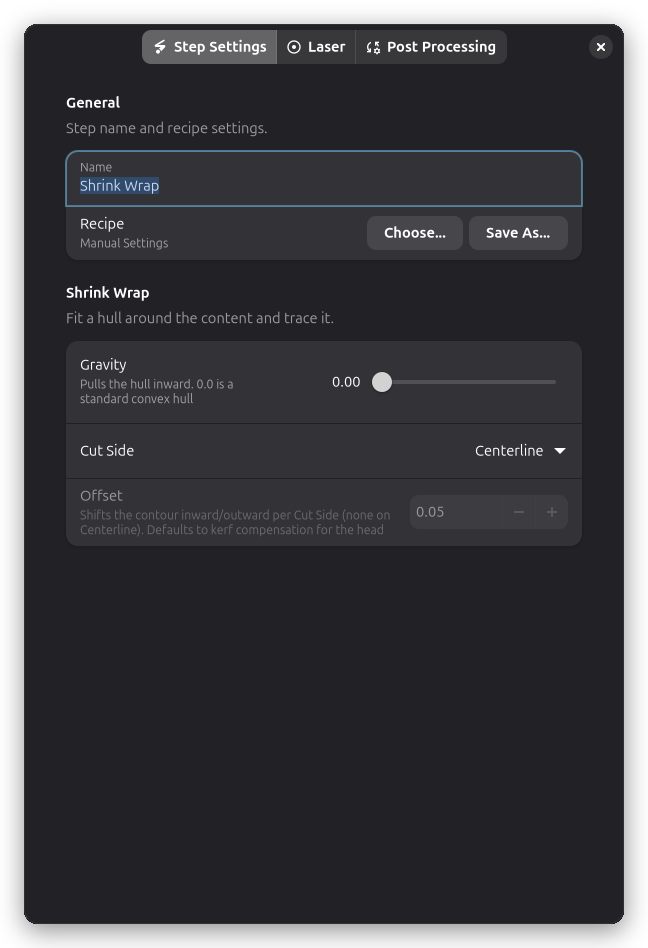
The Shrink Wrap group on the Step Settings tab controls how the hull fits around the content.
Smoothness
Controls how closely the boundary follows object shapes:
High smoothness:
- Follows objects more closely
- More complex path
- Longer cutting time
- Less material waste
Low smoothness:
- Simpler, more rounded path
- Shorter cutting time
- Slightly more material waste
Recommended: Medium smoothness for most cases
Cut Side
Controls where the laser cuts relative to the shrink-wrap path:
| Cut Side | Description | Use For |
|---|---|---|
| Centerline | Cuts directly on the path | Standard cutting |
| Outside | Cuts outside the boundary | Making the cut slightly larger |
| Inside | Cuts inside the boundary | Making the cut slightly smaller |
Offset Distance
Offset (mm):
- How much clearance around the parts
- Distance from objects to the shrink-wrap boundary
- Larger offset = more material left around parts
Typical values:
- 2-3mm: Tight wrap, minimal waste
- 5mm: Comfortable clearance
- 10mm+: Extra material for handling
Why offset matters:
- Too small: Risk cutting into parts
- Too large: Wastes material
- Consider: Kerf width, cutting accuracy
Laser settings
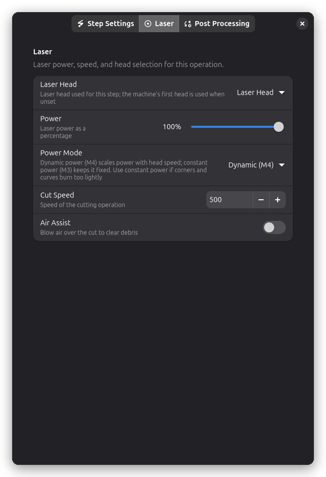
Power, speed, and laser head selection live on the Laser page of the step settings dialog.
Like other cutting operations:
Power (%):
- Laser intensity for cutting
- Same as you'd use for Contour cutting
Speed (mm/min):
- How fast the laser moves
- Match your material's cutting speed
To cut the boundary more than once, add a Multi-Pass post-processor.
Use Cases
Batch Part Production
Scenario: Cutting 20 small parts from a large sheet
Without shrink wrap:
- Cut full sheet boundary
- Waste all material around parts
- Long cutting time
With shrink wrap:
- Cut tight boundary around part group
- Save material for other projects
- Faster cutting (shorter perimeter)
Nesting Optimization
Workflow:
- Nest parts efficiently on sheet
- Group parts into sections
- Shrink wrap each section
- Cut sections separately
Benefits:
- Can remove finished sections while continuing
- Easier handling of cut parts
- Reduced risk of part movement
Material Conservation
Example: Small parts on expensive material
Process:
- Arrange parts tightly
- Shrink wrap with 3mm offset
- Cut free from sheet
- Save remaining material
Result: Maximum material efficiency
Combining with Other Operations
Shrink Wrap + Contour
Common workflow:
- Contour operations on individual parts (cut details)
- Shrink wrap around the group (cut free from sheet)
Execution order:
- First: Cut details in parts (while secured)
- Last: Shrink wrap cuts group free
See Multi-Layer Workflow for details.
Shrink Wrap + Raster
Example: Engraved and cut parts
- Raster engrave logos on parts
- Contour cut part outlines
- Shrink wrap around entire group
Benefits:
- All engraving happens while material is secured
- Final shrink wrap cuts entire batch free
Post-Processing
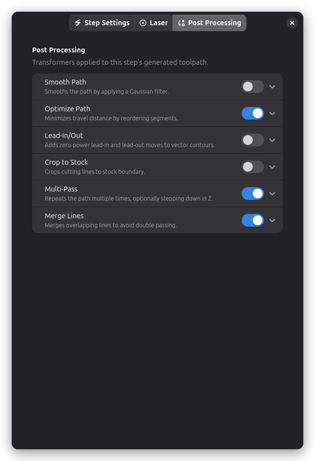
Shrink Wrap operations support several post-processing options:
- Smooth Path - Reduce jagged edges in the boundary path
- Holding Tabs - Keep cut pieces attached to stock material
- Crop to Stock - Limit cuts to material boundary
- Path Optimization - Reduce travel distance
- Multi-Pass - Repeat cuts for thick materials
- Lead-In/Out - Add zero-power approach and exit moves for cleaner cut ends
Part Spacing
Optimal spacing:
- 5-10mm between parts
- Enough for shrink wrap to distinguish separate objects
- Not so much that you waste material
Too close:
- Parts may be wrapped together
- Shrink wrap may bridge gaps
- Difficult to separate after cutting
Too far:
- Wastes material
- Longer cutting time
- Inefficient use of sheet
Material Considerations
Best for:
- Production runs (many identical parts)
- Small parts from large sheets
- Expensive materials (minimize waste)
- Batch cutting jobs
Not ideal for:
- Single large parts
- Parts filling entire sheet
- When you need full sheet cut
Safety
Always:
- Check that boundary doesn't overlap parts
- Verify offset is sufficient
- Preview in 3D Preview
- Test on scrap first
Watch for:
- Shrink wrap cutting into parts (increase offset)
- Parts moving before shrink wrap completes
- Material warping pulling parts out of position
Advanced Techniques
Multiple Shrink Wraps
Create separate boundaries for different groups:
Process:
- Arrange parts into logical groups
- Shrink wrap Group 1 (top parts)
- Shrink wrap Group 2 (bottom parts)
- Cut groups separately
Benefits:
- Remove finished groups during job
- Better organization
- Easier part retrieval
Nested Shrink Wraps
Shrink wrap within a larger boundary:
Example:
- Inner shrink wrap: Small detailed parts
- Outer shrink wrap: Includes larger parts
- Contour: Full sheet boundary
Use for: Complex multi-part layouts
Clearance Testing
Before production run:
- Create shrink wrap
- Preview with 3D Preview
- Verify clearance is adequate
- Check no parts are intersected
- Run test on scrap material
Troubleshooting
Shrink wrap cuts into parts
- Increase: Offset distance
- Check: Parts aren't too close together
- Verify: Shrink wrap path in preview
- Account for: Kerf width (laser beam width)
Boundary doesn't follow shapes
- Increase: Smoothness setting
- Check: Parts are properly selected
- Try: Smaller offset (might be wrapping too far out)
Parts are wrapped together
- Increase: Spacing between parts
- Add: Manual contours around individual parts
- Split: Into multiple shrink wrap operations
Cutting takes too long
- Decrease: Smoothness (simpler path)
- Increase: Offset (straighter boundaries)
- Consider: Multiple smaller shrink wraps
Parts move during cutting
- Add: Small tabs to hold parts (see Holding Tabs)
- Use: Cutting order: inside to outside
- Ensure: Material is flat and secured
- Check: Sheet isn't warped
Technical Details
Algorithm
Shrink wrap uses computational geometry:
- Convex hull - Find outer boundary
- Alpha shape - Shrink toward objects
- Offset - Expand by offset distance
- Simplify - Based on smoothness setting
Path Optimization
The boundary path is optimized for:
- Minimum total length
- Smooth curves (based on smoothness)
- Efficient start/end points
Coordinate System
- Units: Millimeters (mm)
- Precision: 0.01mm typical
- Coordinates: Same as workspace
Related Topics
- Contour Cutting - Cutting individual object outlines
- Multi-Layer Workflow - Combining operations effectively
- Holding Tabs - Keeping parts secure during cutting
- 3D Preview - Previewing cutting paths
- Material Test Grid - Finding optimal cutting settings