Control Panel
The Control Panel at the bottom of the Rayforge window provides manual control over your laser cutter's position, real-time machine status, and a log view for monitoring operations.
Overview
The Control Panel combines several functions into one convenient interface:
- Jog Controls: Manual movement and positioning
- Machine Status: Real-time position and connection state
- Log View: G-code communication and operation history
- Work Coordinate System (WCS): Quick WCS selection
Accessing the Control Panel
The Control Panel is always visible at the bottom of the main window. It can be toggled via:
- Menu: View → Control Panel
- Keyboard Shortcut: Ctrl+L
Connection Required
The jog controls are only available when connected to a machine that supports jogging operations.
Jog Controls
The jog controls provide manual control over your laser cutter's position, allowing you to precisely move the laser head for setup, alignment, and testing purposes.
Homing Controls
Home your machine's axes to establish a reference position:
| Button | Function | Description |
|---|---|---|
| Home X | Homes X axis | Moves X axis to its home position |
| Home Y | Homes Y axis | Moves Y axis to its home position |
| Home Z | Homes Z axis | Moves Z axis to its home position |
| Home All | Homes all axes | Homes all axes simultaneously |
Homing Sequence
It's recommended to home all axes before starting any job to ensure accurate positioning.
Directional Movement
The jog controls provide buttons for directional movement:
| Button | Movement | Keyboard Shortcut |
|---|---|---|
| ↑ | Y+ (Y- if machine is Y-flipped) | Up Arrow |
| ↓ | Y- (Y+ if machine is Y-flipped) | Down Arrow |
| ← | X- (left) | Left Arrow |
| → | X+ (right) | Right Arrow |
| ↖ (top-left) | X- Y± (diagonal) | - |
| ↗ (top-right) | X+ Y± (diagonal) | - |
| ↙ (bottom-left) | X- Y-/+ (diagonal) | - |
| ↘ (bottom-right) | X+ Y-/+ (diagonal) | - |
| Z+ | Z axis up | Page Up |
| Z- | Z axis down | Page Down |
Focus Required
Keyboard shortcuts only work when the main window has focus.
Visual Feedback
The jog buttons provide visual feedback:
- Normal: Button is enabled and safe to use
- Warning (orange): Movement would approach or exceed soft limits
- Disabled: Movement is not supported or machine is not connected
Jog Settings
Configure the behavior of jog operations:
Jog Speed: - Range: 1-10,000 mm/min - Default: 1,000 mm/min - Purpose: Controls how fast the laser head moves
Speed Selection
- Use lower speeds (100-500 mm/min) for precise positioning
- Use higher speeds (1,000-3,000 mm/min) for larger movements
- Very high speeds may cause missed steps on some machines
Jog Distance: - Range: 0.1-1,000 mm - Default: 10.0 mm - Purpose: Controls how far the laser head moves per button press
Distance Selection
- Use small distances (0.1-1.0 mm) for fine-tuning
- Use medium distances (5-20 mm) for general positioning
- Use large distances (50-100 mm) for quick repositioning
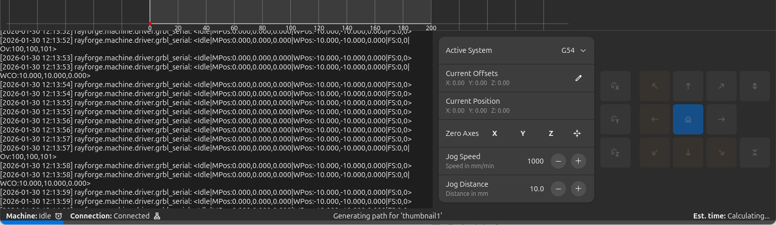
Machine Status Display
The Control Panel displays real-time information about your machine:
Current Position
Shows the laser head's position in the active coordinate system:
- Coordinates are relative to the selected WCS origin
- Updates in real-time as you jog or run jobs
- Format: X, Y, Z values in millimeters
Connection Status
- Connected: Green indicator, machine is responding
- Disconnected: Gray indicator, no machine connection
- Error: Red indicator, connection or communication problem
Machine State
- Idle: Machine is ready for commands
- Run: Job is currently executing
- Hold: Job is paused
- Alarm: Machine is in alarm state
- Home: Homing cycle is in progress
Work Coordinate System (WCS)
The Control Panel provides quick access to Work Coordinate System management.
Active System Selection
Select which coordinate system is currently active:
| Option | Type | Description |
|---|---|---|
| G53 (Machine) | Fixed | Absolute machine coordinates, cannot be changed |
| G54 (Work 1) | User | First work coordinate system |
| G55 (Work 2) | User | Second work coordinate system |
| G56 (Work 3) | User | Third work coordinate system |
| G57 (Work 4) | User | Fourth work coordinate system |
| G58 (Work 5) | User | Fifth work coordinate system |
| G59 (Work 6) | User | Sixth work coordinate system |
Current Offsets
Displays the offset values for the active WCS:
- Shown as (X, Y, Z) in millimeters
- Represents the distance from machine origin to WCS origin
- Updates automatically when WCS offsets change
Setting WCS Zero
Define where the origin of the active WCS should be:
| Button | Function | Description |
|---|---|---|
| Zero X | Set X=0 | Makes current X position the X origin for active WCS |
| Zero Y | Set Y=0 | Makes current Y position the Y origin for active WCS |
| Zero Z | Set Z=0 | Makes current Z position the Z origin for active WCS |
G53 Cannot Be Changed
Zero buttons are disabled when G53 (Machine Coordinates) is selected, as machine coordinates are fixed by hardware.
Setting WCS Workflow
- Connect to your machine and home all axes
- Select the WCS you want to configure (e.g., G54)
- Jog the laser head to the desired origin position
- Click Zero X and Zero Y to set this position as (0, 0)
- The offset is stored in your machine's controller
Log View
The Log View displays G-code communication and operation history:
Log Contents
- Sent Commands: G-code commands sent to the machine
- Responses: Replies and status from the controller
- Error Messages: Any errors or warnings from the machine
- System Messages: Connection status and other system events
Log Features
- Auto-scroll: Automatically scrolls to show latest messages
- Search: Filter log messages by text
- Clear: Clear the log history
- Copy: Copy selected log text to clipboard
Using the Log for Troubleshooting
The log view is invaluable for diagnosing issues:
- Verify commands are being sent correctly
- Check for error messages from the controller
- Monitor connection status and stability
- Review job execution progress
Machine Hours
Rayforge tracks your machine's usage time to help with maintenance scheduling and usage tracking.
Viewing Machine Hours
The machine hours display shows:
- Total Hours: Cumulative time the machine has been in operation
- Job Time: Time spent executing jobs
- Jog Time: Time spent jogging/moving the laser head
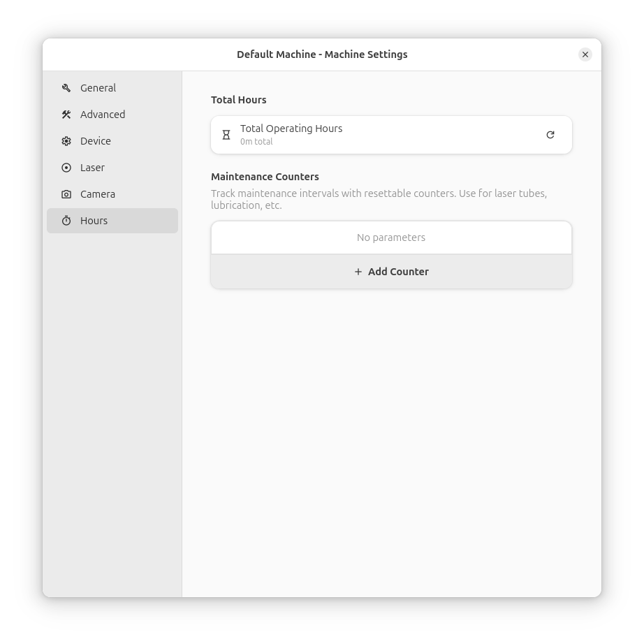
Maintenance Tracking
Use machine hours to schedule maintenance:
- Clean Optics: Every 50-100 hours of use
- Check Belts: Every 200-300 hours of use
- Lubricate Rails: Every 100-200 hours of use
- Replace Tube: Per manufacturer's specification
Resetting Hours
Machine hours can be reset when:
- Performing major maintenance
- Replacing laser tube or diode
- Setting up a new machine profile
Data Loss
Resetting machine hours will clear all historical usage data. Record the value before resetting if you need it for maintenance records.
Machine Compatibility
The Control Panel adapts to your machine's capabilities:
Axis Support
- X/Y Axis: Supported by virtually all laser cutters
- Z Axis: Only available on machines with Z-axis control
- Diagonal Movement: Requires support for both X and Y axes
Machine Types
| Machine Type | Jog Support | Notes |
|---|---|---|
| GRBL (v1.1+) | Full | Supports all jog features |
| Smoothieware | Full | Supports all jog features |
| Custom Controllers | Variable | Depends on implementation |
Safety Features
Soft Limits
When soft limits are enabled in your machine profile:
- Buttons show orange warning when approaching limits
- Movement is automatically limited to prevent exceeding bounds
- Provides visual feedback to prevent crashes
Connection Status
- All controls are disabled when not connected to a machine
- Buttons update sensitivity based on machine state
- Prevents accidental movement during operation
Workflow Tips
Initial Setup
- Connect to Machine: Ensure proper connection
- Home All Axes: Establish reference position
- Set Jog Speed: Choose appropriate speed for task
- Set Jog Distance: Choose appropriate distance for task
Precision Positioning
- Use large distance for rough positioning
- Reduce distance for fine-tuning
- Use keyboard arrows for precise adjustments
- Watch for warning indicators near limits
Testing and Alignment
- Position laser over test area
- Use low speeds for test cuts
- Verify alignment with workpiece
- Adjust position as needed
Monitoring Jobs
- Watch the log view for command execution
- Monitor machine status during operation
- Check position updates for accuracy
- Review error messages if issues occur
Troubleshooting
Jog Controls Not Working
Possible Causes:
- Machine not connected
- Machine doesn't support jogging
- Machine is in alarm or error state
- Soft limits preventing movement
Solutions:
- Check connection status
- Verify machine supports jog commands
- Reset machine if in alarm state
- Check soft limit configuration
Keyboard Shortcuts Not Responding
Possible Causes:
- Main window doesn't have focus
- Another window is active
- System shortcuts intercepting keys
Solutions:
- Click on the main window to give it focus
- Close other windows that might capture keys
- Check system keyboard shortcut settings
Movement Direction Reversed
Possible Causes:
- Y-axis direction configured incorrectly
- Machine orientation different from expected
Solutions:
- Check Y-axis direction in machine profile
- Adjust "Y-axis down" setting if needed
- Test with small movements first
Log Not Updating
Possible Causes:
- Connection not established
- Log view disabled or hidden
- Filter settings hiding messages
Solutions:
- Verify machine is connected
- Check log view is visible
- Clear any active filters
Related Pages:
- Work Coordinate Systems (WCS) - Managing WCS
- Machine Setup - Configure your machine
- Keyboard Shortcuts - Complete shortcut reference
- Main Window - Main interface overview
- Machine Settings - Device configuration