Parametric 2D Sketcher
The Parametric 2D Sketcher is a powerful feature in Rayforge that allows you to create and edit precise, constraint-based 2D designs directly within the application. This feature enables you to design custom parts from scratch without needing external CAD software.
Overview
The sketcher provides a complete set of tools for creating geometric shapes and applying parametric constraints to define precise relationships between elements. This approach ensures your designs maintain their intended geometry even when dimensions are modified.
Creating and Editing Sketches
Creating a New Sketch
- Click the "New Sketch" button in the toolbar or use the main menu
- A new empty sketch workspace will open with the sketch editor interface
- Start creating geometry using the drawing tools from the pie menu or keyboard shortcuts
- Apply constraints to define relationships between elements
- Click "Finish Sketch" to save your work and return to the main workspace
Editing Existing Sketches
- Double-click on a sketch-based workpiece in the main workspace
- Alternatively, select a sketch and choose "Edit Sketch" from the context menu
- Make your modifications using the same tools and constraints
- Click "Finish Sketch" to save changes or "Cancel Sketch" to discard them
Creating 2D Geometry
The sketcher supports creating the following basic geometric elements:
- Lines: Draw straight line segments between points
- Circles: Create circles by defining a center point and radius
- Arcs: Draw arcs by specifying a center point, start point, and end point
- Fills: Fill closed regions to create solid areas
These elements form the foundation of your 2D designs and can be combined to create complex shapes. Fills are particularly useful for creating solid regions that will be engraved or cut as a single piece.
Parametric Constraint System
The constraint system is the core of the parametric sketcher, allowing you to define precise geometric relationships:
Geometric Constraints
- Coincident: Forces two points to occupy the same location
- Vertical: Constrains a line to be perfectly vertical
- Horizontal: Constrains a line to be perfectly horizontal
- Tangent: Makes a line tangent to a circle or arc
- Perpendicular: Forces two lines, a line and an arc/circle, or two arcs/circles to meet at 90 degrees
- Point on Line/Shape: Constrains a point to lie on a line, arc, or circle
- Symmetry: Creates symmetrical relationships between elements. Supports two modes:
- Point Symmetry: Select 3 points (first is the center)
- Line Symmetry: Select 2 points and 1 line (the line is the axis)
Dimensional Constraints
- Distance: Sets the exact distance between two points or along a line
- Diameter: Defines the diameter of a circle
- Radius: Sets the radius of a circle or arc
- Equal Length/Radius: Forces multiple elements (lines, arcs, or circles) to have the same length or radius
- Equal Distance: Forces the distance between two point pairs to be equal
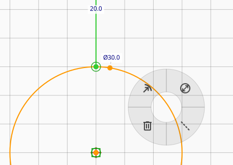
Pie Menu Interface
The sketcher features a context-aware pie menu that provides quick access to all drawing and constraint tools. This radial menu appears when you right-click in the sketch workspace and adapts based on your current context and selection.
The pie menu items dynamically show available options based on what you have selected. For example, when clicking on empty space, you'll see drawing tools. When clicking on selected geometry, you'll see applicable constraints.
Keyboard Shortcuts
The sketcher provides keyboard shortcuts for efficient workflow:
Tool Shortcuts
Space: Select toolG+L: Line toolG+A: Arc toolG+C: Circle toolG+F: Fill Area toolG+N: Toggle construction mode on selection
Constraint Shortcuts
H: Apply Horizontal constraintV: Apply Vertical constraintT: Apply Tangent constraintN: Apply Perpendicular constraintE: Apply Equal constraintOorC: Apply Alignment constraint (Coincident)S: Apply Symmetry constraintK+D: Apply Distance constraintK+R: Apply Radius constraintK+O: Apply Diameter constraint
General Shortcuts
Ctrl+Z: UndoCtrl+YorCtrl+Shift+Z: RedoDelete: Delete selected elementsEscape: Cancel current operation or deselectF: Fit view to content
Construction Mode
Construction mode allows you to mark entities as "construction geometry" - helper elements used to guide your design but not part of the final output. Construction entities are displayed differently (typically as dashed lines) and are not included when the sketch is used for laser cutting or engraving.
To toggle construction mode:
- Select one or more entities
- Press N or G+N, or use the Construction option in the pie menu
Construction entities are useful for: - Creating reference lines and circles - Defining temporary geometry for alignment - Building complex shapes from a framework of guides
Import and Export
Saving Sketches
You can save your 2D sketches to files for reuse in other projects. All parametric constraints are preserved when saving, ensuring your designs maintain their geometric relationships.
Importing Sketches
Saved sketches can be imported into any workspace, allowing you to create a library of commonly used design elements. The import process maintains all constraints and dimensional relationships.
Workflow Tips
- Start with Rough Geometry: Create basic shapes first, then refine with constraints
- Use Constraints Early: Apply constraints as you build to maintain design intent
- Check Constraint Status: The system indicates when sketches are fully constrained
- Utilize Symmetry: Symmetry constraints can significantly speed up complex designs
- Iterate and Refine: Don't hesitate to modify constraints to achieve the desired result
Editing Features
- Full Undo/Redo Support: The entire sketch state is saved with each operation
- Dynamic Cursor: The cursor changes to reflect the active drawing tool
- Constraint Visualization: Applied constraints are clearly indicated in the interface
- Real-time Updates: Changes to constraints immediately update the geometry
- Double-Click Editing: Double-click on dimensional constraints (Distance, Radius, Diameter) opens a dialog to edit their values
- Parametric Expressions: Dimensional constraints support expressions, allowing values to be
calculated from other parameters (e.g.,
width/2for a radius that's half the width)