


Bed Mesh
Large work surfaces are rarely perfectly flat. When the bed height varies more than your laser's depth of focus, cuts come out inconsistent over the material. The bed mesh feature probes the surface height on a grid and compensates the toolpath's Z axis so the focal point follows the real surface.
Requirements
Bed meshing needs a machine with a Z axis and a driver that supports probing (GRBL, Marlin, Smoothie, and OctoPrint today). The Bed Mesh page only appears in Settings → Machine when both are the case. The page is located after the Device page.
Probing the Bed
Open Settings → Machine and navigate to the Bed Mesh page.
- Probe Grid: Define the area to probe (X/Y origin, width, height) and the grid density (columns and rows). The page shows the resulting number of probe points and estimates the probing duration. Denser grids follow the surface more accurately but take longer to probe.
- Probing: Configure the probing feed rate, how far the head may travel down searching for the surface at each point (Maximum Travel), and the Safe Z height used to move between points. Safe Z is a position, not a distance; it may be negative on machines that home Z upward.
- Click Start Probing. The machine visits every grid point in a serpentine pattern, touches the surface at each one, and the 3D view fills in live as results arrive. You can stop the run at any time; the mesh is only saved when the full grid completes.
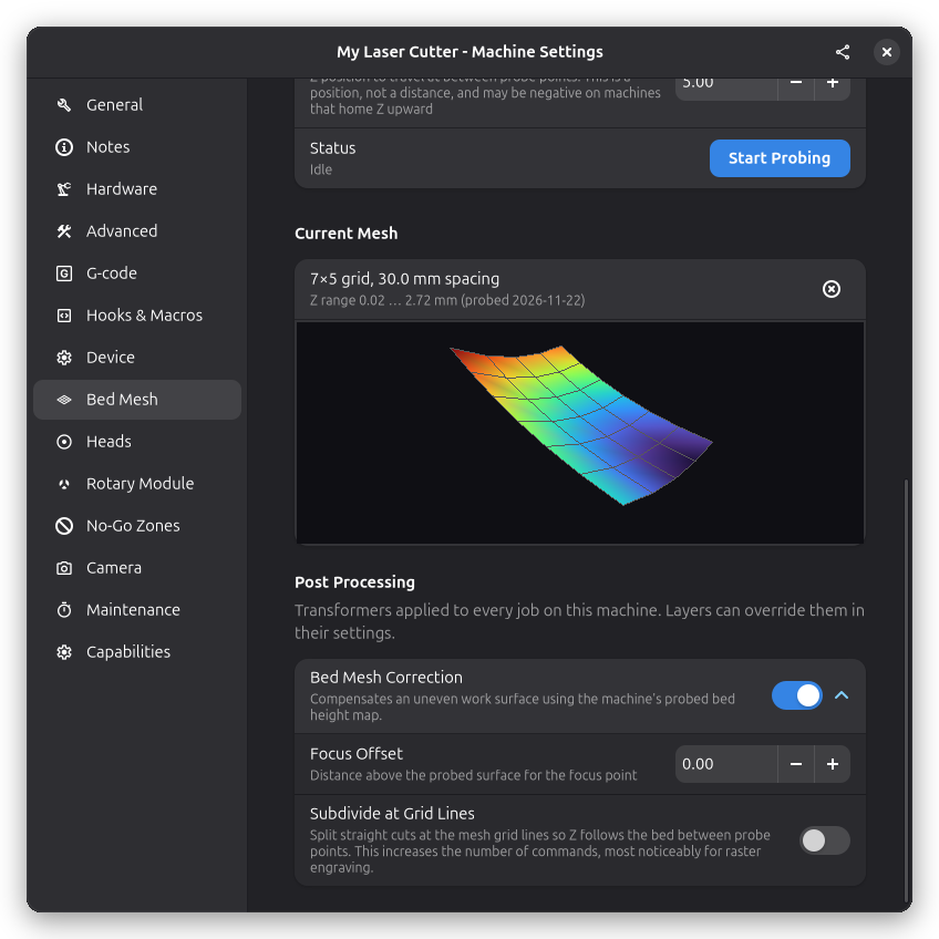
The mesh is stored with the machine profile and shown as a colored 3D surface: blue areas are lower, red areas higher. Use the Delete Mesh button to remove the mesh again if you no longer want height compensation.
the probe, and make sure your probe tip (or laser crosshair) can actually reach the surface at every grid point. :::
Applying the Mesh
Probing only records the height map — applying it is controlled per job:
- Apply to Jobs by Default: Enable this switch on the Bed Mesh page to compensate the Z axis of every job on this machine.
- Per-layer override: In a layer's settings (Layer Settings → Post Processing), the machine default shows up with Customize and Disable actions. Customizing copies the correction into the layer, where you can adjust the Focus Offset (how far above the probed surface the focus point should be); disabling turns the correction off for that layer only. Removing the layer's entry falls back to the machine default.
- Subdivide at Grid Lines: Enable this switch to split straight cuts at the mesh grid lines so Z follows the bed between probe points. It generates more commands, most noticeably for raster engraving.
The correction applies to cutting moves and travel moves alike, and arcs stay arcs (they become helical). It runs on the final toolpath in machine coordinates and accounts for the active work coordinate system's Z offset, so a job at Z 0 follows the bed height at the focus offset rather than the raw probed machine Z.
If your machine's postscript returns to the origin, add a Z lift before that move (for example
G0 Z0, using a height that is safe on your machine) so the head does not travel home at the last
cut height.
Related Pages
- Hardware Settings - Machine dimensions and axis configuration
- Device Settings - Connection and controller options
- 3D View - 3D toolpath visualization